[0018]More concretely, it is a first object of the present invention to reduce the load of each server and a second object to reduce the dependency of the query processing on the network. It is a third object to shorten the time of response to each query, and a fourth object to reduce the load the network. It is a fifth object to reduce the storage capacity of each client, a sixth object to reduce the updating cost of each replica, and a seventh object to improve the
hit ratio of each replica.
[0019]In order to achieve the first to third objects described above, the present invention provides a
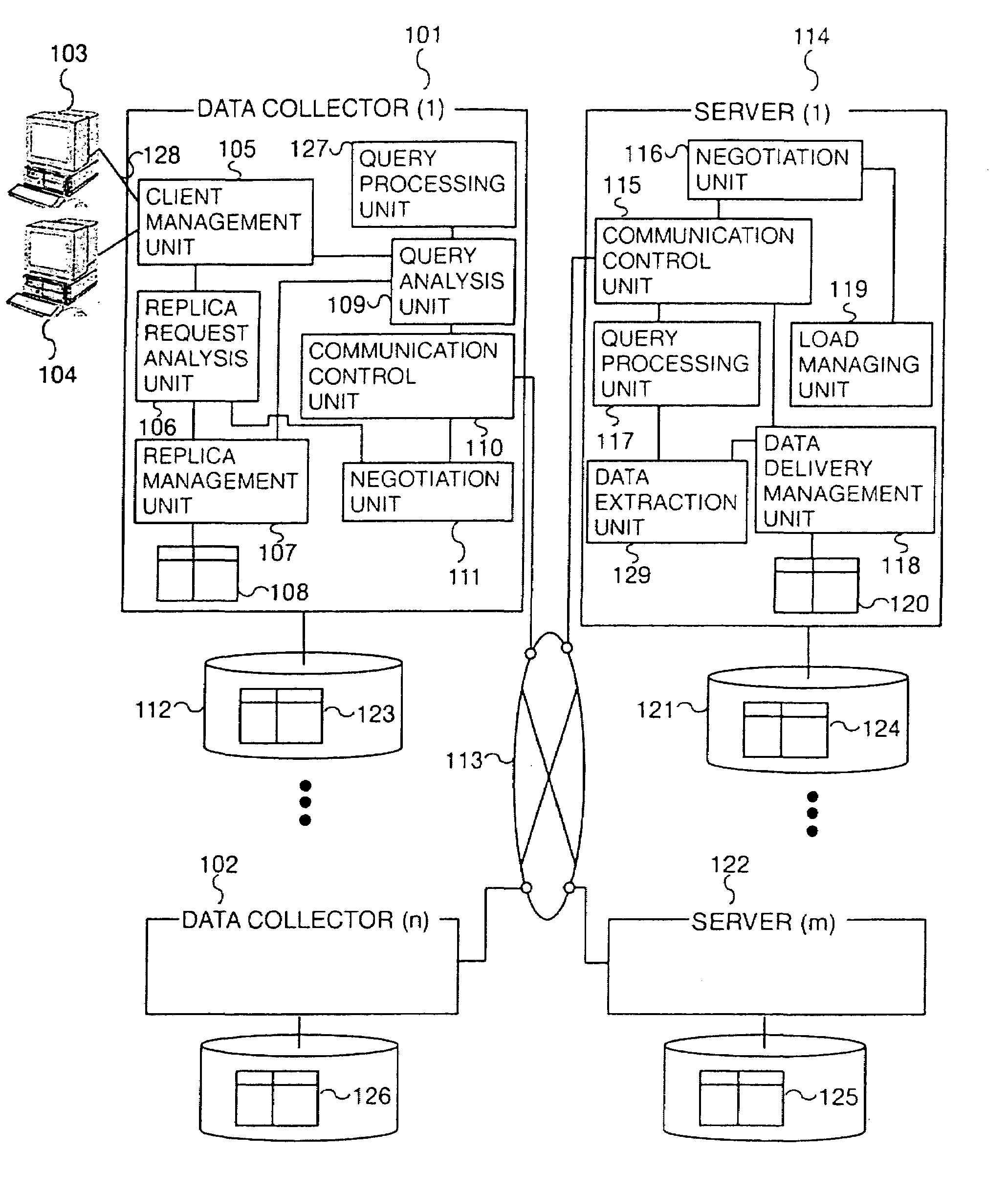
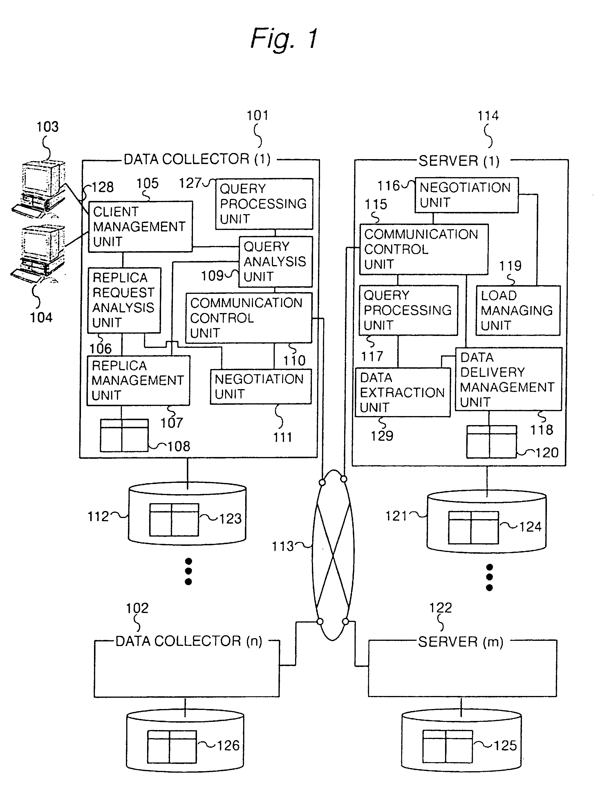
data warehouse system having a data collector for creating / managing replicas of the data in a server used for processing queries from clients, so that those replicas created in the data collector are used as much as possible for processing queries from clients. Because the data collector processes queries in such a way, less queries are transferred to the server, thereby the reduction of the load applied on the server, which is the first object, can be achieved. Furthermore, because the data collector can also create replicas of data in the server, those replicas created in the data collector can be used for processing queries from clients when the network connected to the server goes down, thereby the reduction of the dependency of query processings on the network, which is the second object, can be achieved. Furthermore, because the data collector can also use the replicas of only the minimum necessary data for processing queries from a limited number of clients and processes no query in the server, the shortening of the
response time to each query, which is the third object, can be achieved. To achieve this third object, query processings in the server are avoided especially to prevent the server from an increase of the load to be caused by accesses from many clients and management of a
mass of data, which result in high costs for processing those many queries.
[0020]More concretely, according to the present invention, each query is processed as follows. The data collector decides if it is possible to process a query from a client itself or whether the query should be processed in another cooperative data collector or whether it should be transferred to a server. If the data collector itself or another cooperative data collector can process the query, the data collector will process the query. With such use of other cooperative data collectors, many queries can be processed in those data collectors, thereby the first to third objects can be achieved. Furthermore, because only some of the queries, which cannot be processed by the data collector and any other cooperative data collectors, are transferred to a server, the amount of data to be processed in the server becomes less, thereby the load on the server can be reduced and less result data is sent back from the server to clients. The reduction of the load on the object network, which is the fourth object, can thus be achieved.
[0021]Furthermore, in order to solve the problems which arise when replicas are simply created and to achieve the fourth to sixth objects, the data collector is associated with other data collectors as needed, so that clients who can share data are grouped and replicas are created for such a group of clients and the replicas are shared among those clients in the group. Because each replica is shared by clients in such a way, the amount of data to be transferred from the server to the data collector is reduced, thereby the load of the network is reduced. According to the present invention, the data collector creates replicas. Thus, it is possible to reduce the capacity of the storage unit required by each client, which is the fifth object, as well as to reduce the capacity of the storage unit required by the data collector through sharing of replicas among data collectors. Furthermore, because replicas are shared among data collectors, the number of replicas in the whole system can be reduced, thereby the reduction of the updating cost, which is the sixth object, can also be achieved.
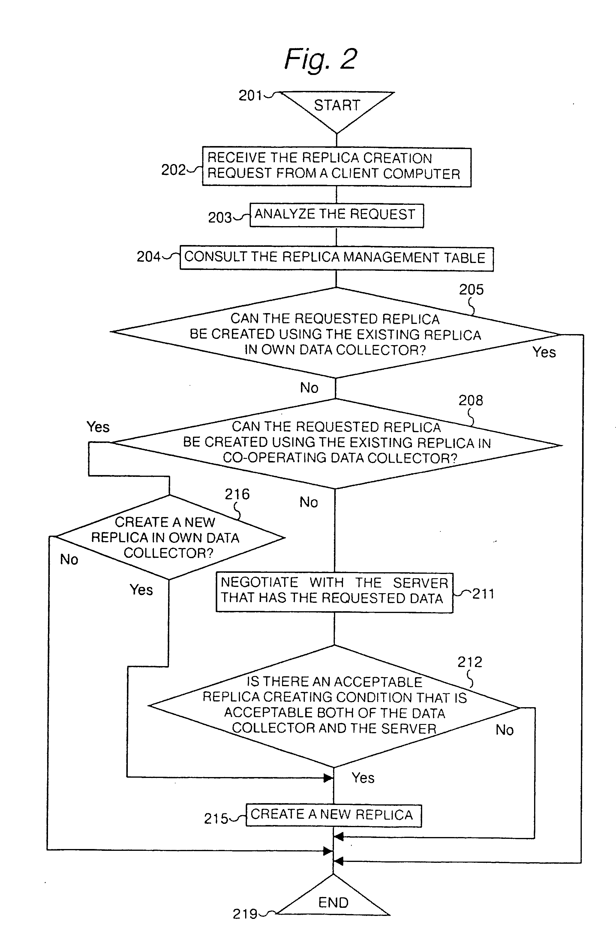
[0022]A replica can be created so as to satisfy part or the whole of each replica creation request as follows. At first, the data collector accepts a replica creation request from a client. The request includes conditions such as the
data quality, the precision, freshness, and priority of the data given from a user through the client, as well as the condition of the
data collecting range. The data collector then holds the request. After that, the data collector negotiates with a server which supplies the object data considering the values of available resources, such as the storage unit capacity, the CPU performance, etc., thereby creating a replica which satisfies part or the whole of the replica creation request. Because a replica creation request is given from each user, it is possible to collect the data wanted by the user, thereby the
hit ratio of each replica can be improved to achieve the seventh object. Furthermore, because the
data quality is adjusted when each replica is created, it is possible to create the object replica in a proper size according to the
computer resources available for the data collector, thereby the reduction of the load on the object network, which is the fourth object, can be achieved and the reduction of the capacity of the storage unit of each client and the data collector, which is the fifth object, can be achieved. In addition, the reduction of the updating cost for each replica, which is the sixth object, can be achieved.
[0023]When in updating a replica, the pull method controlled by each client and the pushing method controlled by each server are combined so as to reduce the load on the server while considering the request of each client for data. The load of the server when updating a replica, which is the first object, can thus be reduced.

