Fluidized bed granulation coating device and fluidized bed granulation coating method

a technology of fluidized bed and coating device, which is applied in the direction of material granulation, lighting and heating apparatus, furniture, etc., can solve the problems of difficult to expect the complete classification effect, large particle size distribution of products to be discharged, and inability to obtain products to be dried completely

Inactive Publication Date: 2006-09-26
FREUNT IND
View PDF7 Cites 7 Cited by
  • Summary
  • Abstract
  • Description
  • Claims
  • Application Information

AI Technical Summary

Benefits of technology

[0042]However, in the configuration of sequentially moving the plurality of drying chambers similarly to the above-mentioned configuration, while being supplied into one drying chamber, the powder grains are dried in another drying chamber and the dried powder grains are at one discharged from the powder grain exhaust port of still another drying chamber. Namely, the same drying process as that performed by a so-called continuous method can be performed. Meanwhile, the drying process of powder grains is performed by a batch method until the powder grains are supplied and discharged. More specifically, the configuration of the present invention has both merits of the continuous method and the batch method simultaneously and so is capable of continuously performing the reception, drying, and discharge of powder grains and, at the same time, of sufficiently drying the powder grains by a batch method.
[0043]Therefore, by using the fluidized-bed granulation coating device and the fluidized-bed granulation coating method according to the present invention, the powder grains can be supplied from upward and the powder grain products granulated and dried from downward can be continuously manufactured. Thus, even when mass production is to be performed, scaling up the device is not required and no problems in quality assurance or the like occur when the device is scaled up.

Problems solved by technology

However, since particles of all stages of a granulation process are included in a fluidized-bed obtained by using the continuous type thereof, the particles are classified by the pneumatic classification and are discharged and so there are such drawbacks that classification effect is difficult to expect entirely and a particle size distribution of products to be discharged becomes large, and that products to be dried completely are not obtained since the granulation substances are discharged from a fluidizing chamber in which binder liquids are continuously sprayed, and the like.
For example, the device disclosed in Japanese Patent Laid-open No. 62-282629 is provided with a drying chamber adjacent to a granulation chamber, but the drying chamber has a drying effect and contributes to no improvement in a particle size distribution.
However, these devices are each suggested as a system and they themselves are not necessarily improved.
Therefore, non-uniformity of particle sizes of the products obtained by the continuous type remains fatefully without being improved.
However, the device has a problem of scaling up the fluidized-bed device as the production thereof is scaled up.
More particularly, upsizing the device causes extensions of the time required for a batch in comparison to a small-sized device, so that the production capacity per unit time does not become proportional to a charge amount but will be below the charge amount.
Even from the viewpoint of operation, the larger the device becomes, the more difficult maintaining a good fluidizing condition becomes and faulty fluidizing conditions such as channeling, bubbling, slagging or the like are likely to occur.
As described above, since it is not favorable to upsize the fluidized-bed device to a more degree than a certain degree, small-sized devices with used experience are arranged in parallel and the same granulating processes is performed by at least two of the small-sized devices.
However, in this method, it is likely that there will arise problems of no improvement in a floor area for setting the devices and / or in production efficiency per worker as the production scale is increased, and of being unable to enjoy merits of mass production, and further of non-uniform quality of the granulation substances owing to unevenness of respective operating conditions between the devices.
This is because there is also the fact that, in the fluidized-beds, the number of operating conditions is large in comparison with other granulating methods and this method is more easily developed than other methods owing to an influence of the unevenness.

Method used


Image

  • Fluidized bed granulation coating device and fluidized bed granulation coating method
  • Fluidized bed granulation coating device and fluidized bed granulation coating method
  • Fluidized bed granulation coating device and fluidized bed granulation coating method

Examples


embodiment 1

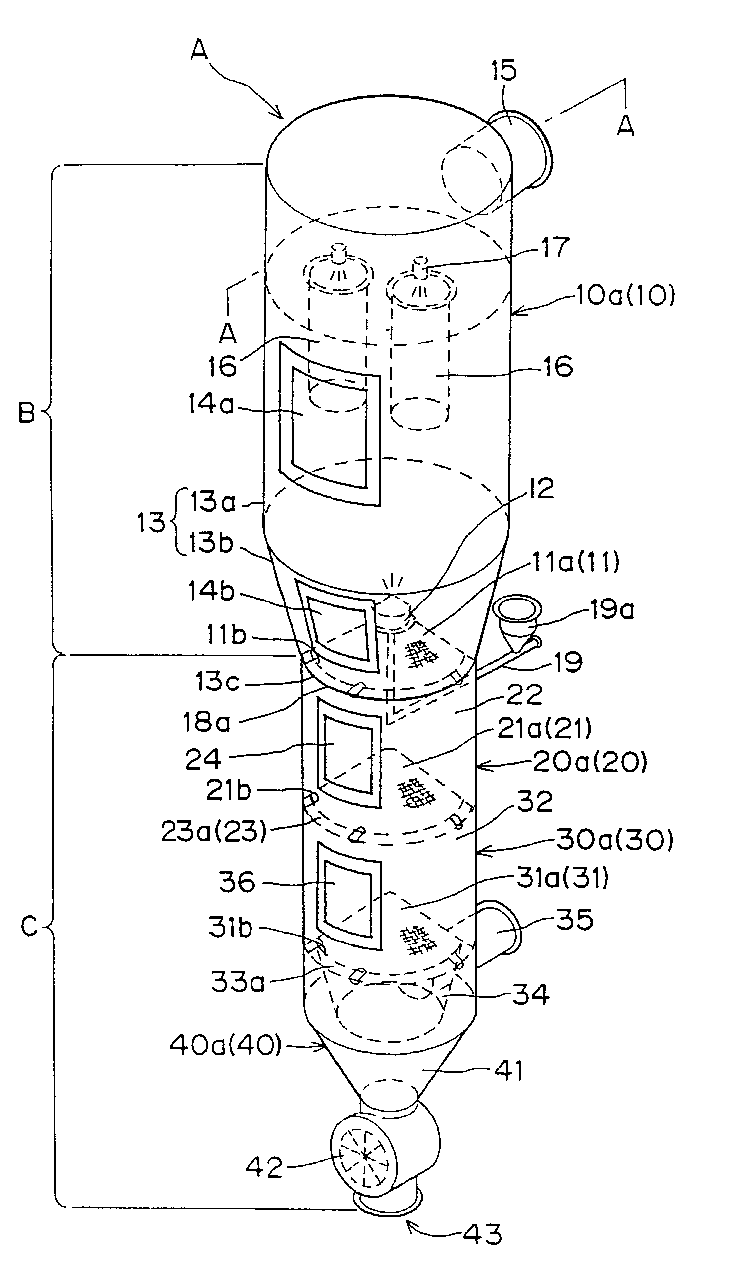
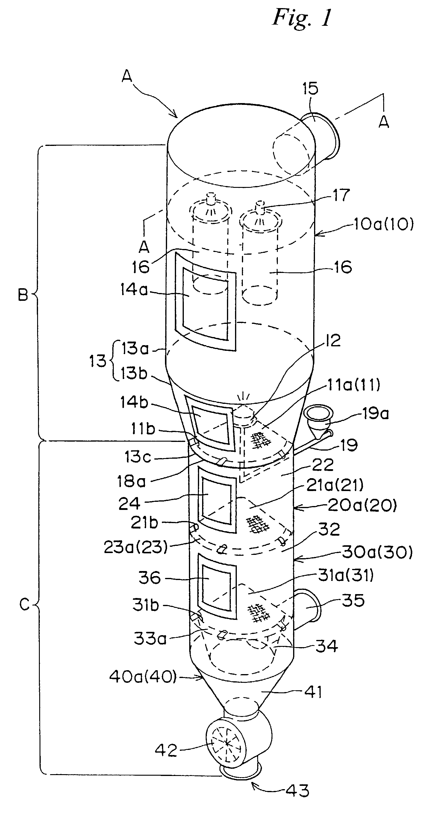
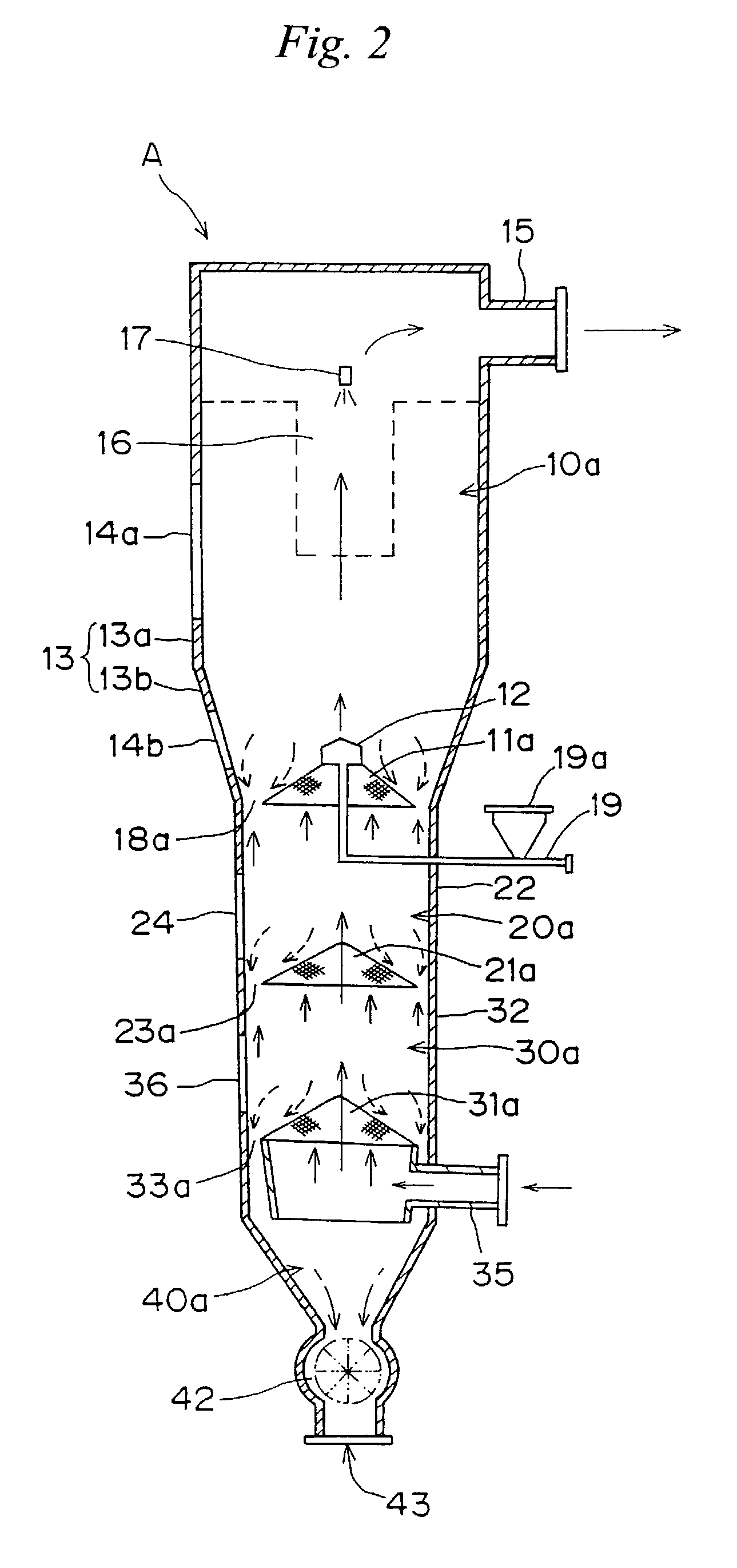
[0059]An embodiment of the present invention will be described below and in detail with reference to the drawings. FIG. 1 is a perspective view showing a fluidized-bed granulation coating device according to the present invention. FIG. 2 is a cross-sectional view of the fluidized-bed granulation coating device shown in FIG. 1.

[0060]A fluidized-bed granulation coating device, as shown in FIG. 1, comprises a main body A constituted by a large-diameter cylinder portion B and a small-diameter cylinder portion C, which are formed in a straightly cylindrical shape. The main body A is formed in a substantially vertical cylindrical shape, i.e., as a straightly cylindrical type. The cylindrical interior of the main body A is sequentially partitioned and divided vertically into a plurality of sections 10, 20, 30 and 40 by using partition means 11, 21 and 31.

[0061]The large-diameter cylinder portion B and the small-diameter cylinder portion C are divided by the partition means 11, and the inte...

embodiment 2

[0076]In this embodiment, the case where the granulation of powder grains is performed by using a fluidized-bed granulation coating device having the above-mentioned configuration will be described below. The exhaust pipe 15 provided at the upper portion of the main body A is connected to an intake source and the suction thereof is made, so that a dried fluidized-bed forming-gas (indicated by a solid-line arrow in FIG. 2) is introduce into the gas-supply chamber 34 from the gas-supply pipe 35.

[0077]The fluidized-bed forming-gas fed in the gas-supply chamber 34 is, as shown in FIG. 2, fed into the cylinder 32 of the drying section 30a through the mesh of the partition wire net 31a. The fluidized-bed forming-gas fed into the drying section 30a is also fed into the cylinder 22 of the drying section 20a through the slit 23a and the mesh of the partition wire net 21a. The fluidized-bed forming-gas fed into the drying section 20a is further fed into the granulating section 10a through the...

embodiment 3

[0089]In this embodiment, a modified example of the partition means will be described. The case where, as a partition means, the partition wire nets 11a, 21a and 31a obtained by making predetermined mesh wire nets each formed in a substantially conical shape are used has been described above. However, a partition means having another configuration may be used.

[0090]For example, as shown in FIG. 3A, a partition wire net 50 (indicated by a broken lines in FIG. 3A) may be formed such that a predetermined mesh wire net is formed in an inverted conical shape and a falling port 51 in which the granulated powder grains fall is provided at the center thereof. Pneumatic classification using the fluidized-bed forming-gas is made at the falling port 51.

[0091]In the case shown in FIG. 3B, a partition wire net 52 (indicated by a broken lines in FIG. 3B) obtained by making a predetermined mesh wire net formed in a plate shape may be constituted to have such an inclination that the granulated powd...


PUM

PropertyMeasurementUnit
gravityaaaaaaaaaa
flow ratesaaaaaaaaaa
solubilityaaaaaaaaaa

Abstract

Under the granulating section 10a for performing fluidized-bed granulation coating of powder grains, a drying section 20a for drying powder grains granulated is provided. A drying section 30a for drying the powder grains that are not sufficiently dried is provided under the drying section 20a. A product discharging section 40a for discharging a dried product is provided under the drying section 30a. A fluidized-bed forming-gas is supplied downward to upward, and granulation and dryness are continuously performed by the fluidized-bed forming-gas, and the powder grains moved from the granulating section to the drying section located immediately thereunder are pneumatic classified.

Description

REFERENCE TO PRIOR APPLICATION[0001]This application is entitled to the benefit of and incorporates by reference essential subject matter disclosed in PCT Patent Application No. PCT / JP01 / 03553 filed on 25 Apr. 2001; Japanese Application No. 2000-132421 filed 01 May 2000; and Japanese Application No. 2001-17840 filed 26 Jan. 2001.TECHNICAL FIELD[0002]The present invention relates to a granulation coating technique for performing continuously a process such as granulation, coating, mixing, agitation, drying or the like of powder grains with the powder grains fluidized.BACKGROUND ART[0003]A fluidized-bed device can perform granulation coating and drying of pharmaceuticals, food or the like within a single device and has an airtight structure, so that it is a suitable device in view of GMP. Therefore, granulation substances obtained by using this have characteristics of comparatively porous and amorphous shapes and good solubility, and so are widely utilized.[0004]While there are many k...

Claims


Application Information

Patent Timeline
Patent Type & Authority Patents(United States)
IPC IPC(8): B05B17/00F26B5/00B01J2/00B01J2/16F26B3/08
CPCB01J2/006F26B3/08B01J2/16Y10S118/05B05C19/02
Inventor TAKEI, NARIMICHIITOU, TAKEHIKOWATANABE, TAKASHIUNOSAWA, KAZUOMIOOISHI, HIROYUKI
Owner FREUNT IND
Why Eureka
Try Eureka