Proximity sensing based on antenna impedance variation

a technology of antenna impedance variation and proximity detection, applied in the direction of instruments, electric signalling details, sustainable buildings, etc., can solve the problems of consuming more power of the mouse, affecting the detection effect, so as to achieve a simple and economic manner of detection

a technology of antenna impedance variation and proximity detection, applied in the direction of instruments, electric signalling details, sustainable buildings, etc., can solve the problems of consuming more power of the mouse, affecting the detection effect, so as to achieve a simple and economic manner of detection

US7113087B1Inactive Publication Date: 2006-09-26MICROSOFT TECH LICENSING LLC

Image

  • Proximity sensing based on antenna impedance variation
  • Proximity sensing based on antenna impedance variation
  • Proximity sensing based on antenna impedance variation

Examples


Embodiment Construction

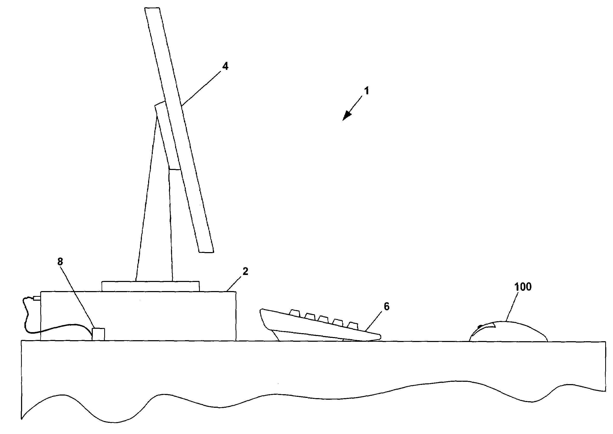
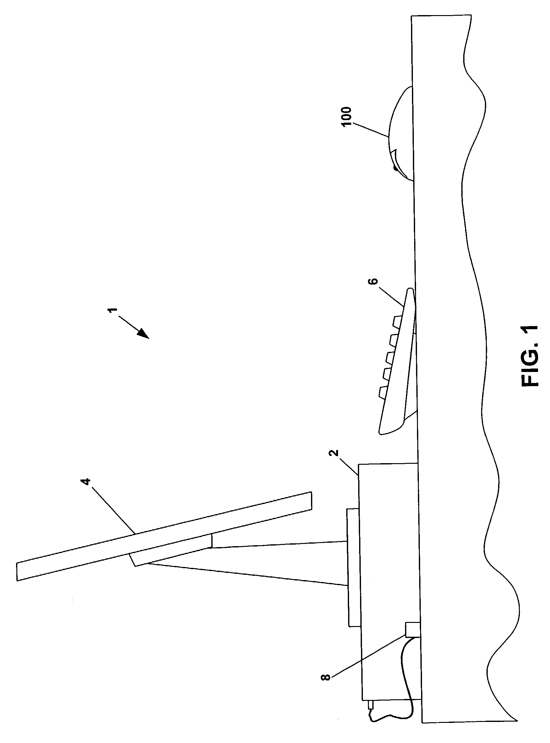
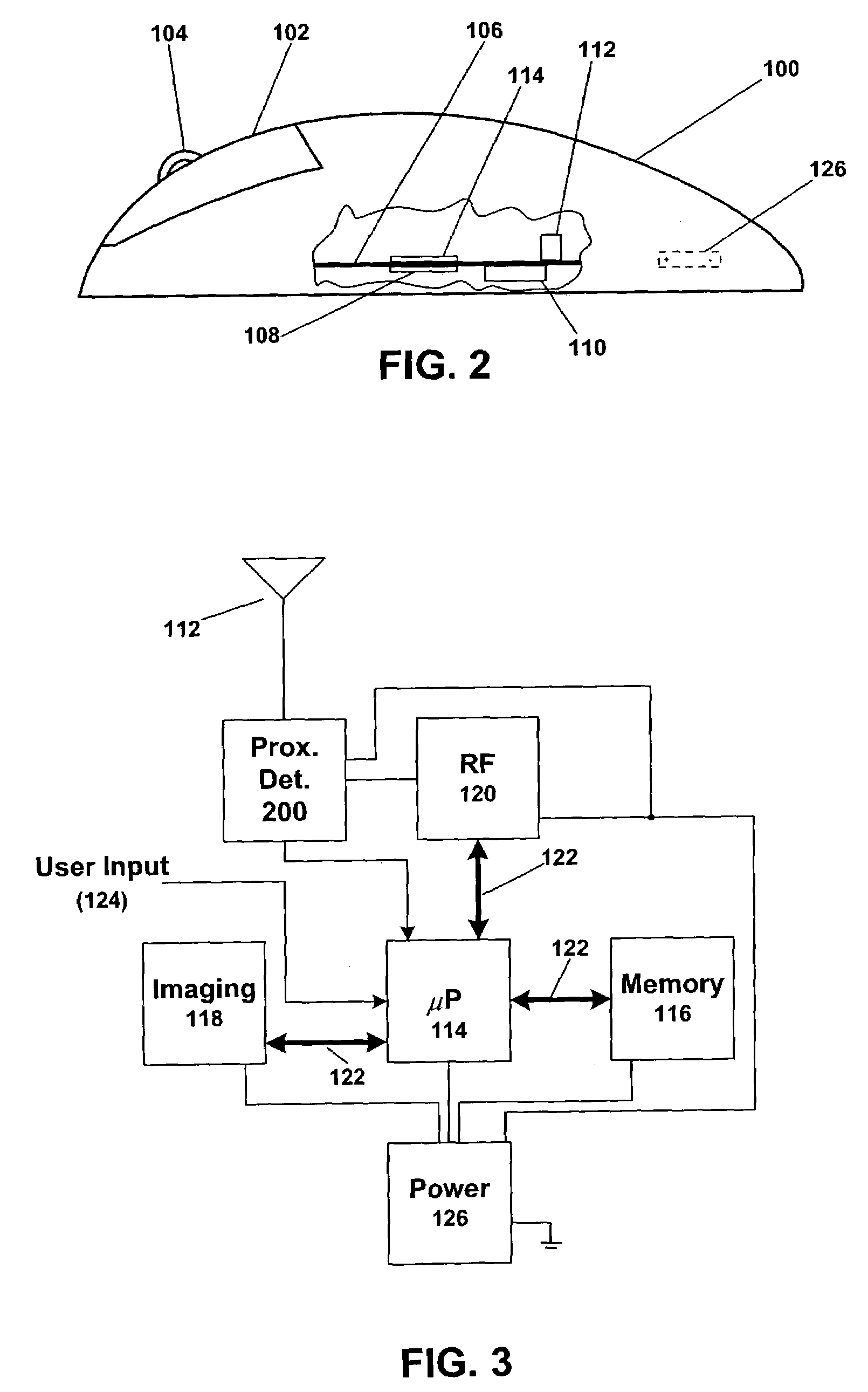
[0018]An application of the invention within a wireless, optically tracking computer mouse is described by way of example. However, the invention has much wider-ranging application, and can be used in numerous devices wherein it would be advantageous to conserve battery power during periods of non-use. The invention also has useful application in other data input devices, both portable and non-portable. The invention finds particularly useful application (but is not limited to) battery powered devices which communicate via RF transmission, which are intermittently used, and which are generally left on over extended periods of time so as to provide ready usability when needed. Such devices include (but are not limited to) portable computers, personal data assistants (PDAs), tablet computers, cellular phones, pagers and wireless computer peripherals, e.g., mice and keyboards. The proximity sensing aspects of the present invention are not limited to power management, and can also be im...


PUM


Abstract

Proximity of a user body part can be detected by measuring the effects such proximity has on antenna impedance mismatches. The amount of mismatch affects the amount of RF signal energy reflected back into a transmission line connecting the antenna to a RF signal source. A directional coupler has a main line electrically connected to the transmission line, as well as a coupled line. The directional coupler produces a signal on its coupled line in relation to the magnitude of reflected energy on the transmission line; the amount of reflected energy varies in response to how well the antenna impedance matches the transmission line impedance. A signal detector is electrically connected to the coupled line, and responds to signals produced in the coupled line by the main line. The signal detector output is then used to determine whether a body part is in proximity. Other aspects the invention include an adaptive algorithm to adjust a threshold for proximity determination.

Description

FIELD OF THE INVENTION[0001]This invention relates to systems and methods for proximity detection in electronic devices. More particularly, this invention relates to systems and methods for detecting the approach or presence of a user by measuring effects of changes in antenna impedance matching.BACKGROUND OF THE INVENTION[0002]Detecting proximity or approach of a user's hand (or other body part) permits an electronic device to automatically change from one state to another based upon that approach or proximity. One important application for this is in conjunction with power management. For example, a device can be configured to have “sleep” and “awake” states. During a sleep state, which can correspond to periods of device non-use, various components and functions can be turned off so as to minimize power consumption. Non-use of a device often corresponds to periods when a user is not holding or near the device. If the device can detect the user's presence and / or contact, the devic...

Claims


Application Information

Patent Timeline
26 Sep 2006
Publication
US7113087B1
IPC
G08B1/08
CPC
G01V3/101; G06F1/3203; G06F1/3215; G06F1/3231; G06F3/03543; G06F1/3259; Y02B60/148; Y02B60/1253
Inventors
CASEBOLT, MARK W.; RANTA, CRAIG S.