Digital video recording system

Inactive Publication Date: 2006-10-03
ADT SERVICES
View PDF18 Cites 70 Cited by
  • Summary
  • Abstract
  • Description
  • Claims
  • Application Information

AI Technical Summary

Benefits of technology

[0024]A further object of the present invention is a DVR system in which motion is specifically excluded as an aid in the encoder. The current invention relies on the simpler concept of change in an image area, wherein any change in a specified area results in the storing of that area for the current image. Any area or region in an image which is not changed from a reference image is not stored. This simplification dramatically reduces processor requirements and the amount of data which must be stored. No motion vector searches must be performed and no image data is stored unless changed from a reference. No distinction between spatial and temporal blocks is required and no coding of blocks is performed. Rather, each block with changes detected is simply encoded using a standard image compression algorithm such as JPEG.
[0025]A further object of the present invention is a DVR system in which only intensity information is used in the identification of changed image areas, allowing for fast identification of the image areas to be compressed and stored. This allows for continuous recording of images at low data rates which results in many days of storage being available.
[0026]A further object of the present

Problems solved by technology

This process has a number of problems associated with it.
However, this is seldom done because of the expense or impracticality of doing so.
This residual magnetization degrades the resolution capability of the tape and resulting quality of the recorded images.
One problem law enforcement officers or security personnel have with the recording systems described above is that the poor quality of the recorded images makes it difficult to discern features or details of the events captured on the tape, including the identification of persons.
Another problem with conventional recording systems is that simply because an event of significance has occurred, recording does not stop.
In situations where time may be critical, the resulting delay is very undesirable.
However, there is no indication of how the motion detection is performed and specifically, the motion is not used to aid in the size reduction of the stored data.
The '551 Logan et al. system cannot be readily adapted to systems with a large or unli

Method used


Image

  • Digital video recording system
  • Digital video recording system
  • Digital video recording system

Examples


Embodiment Construction

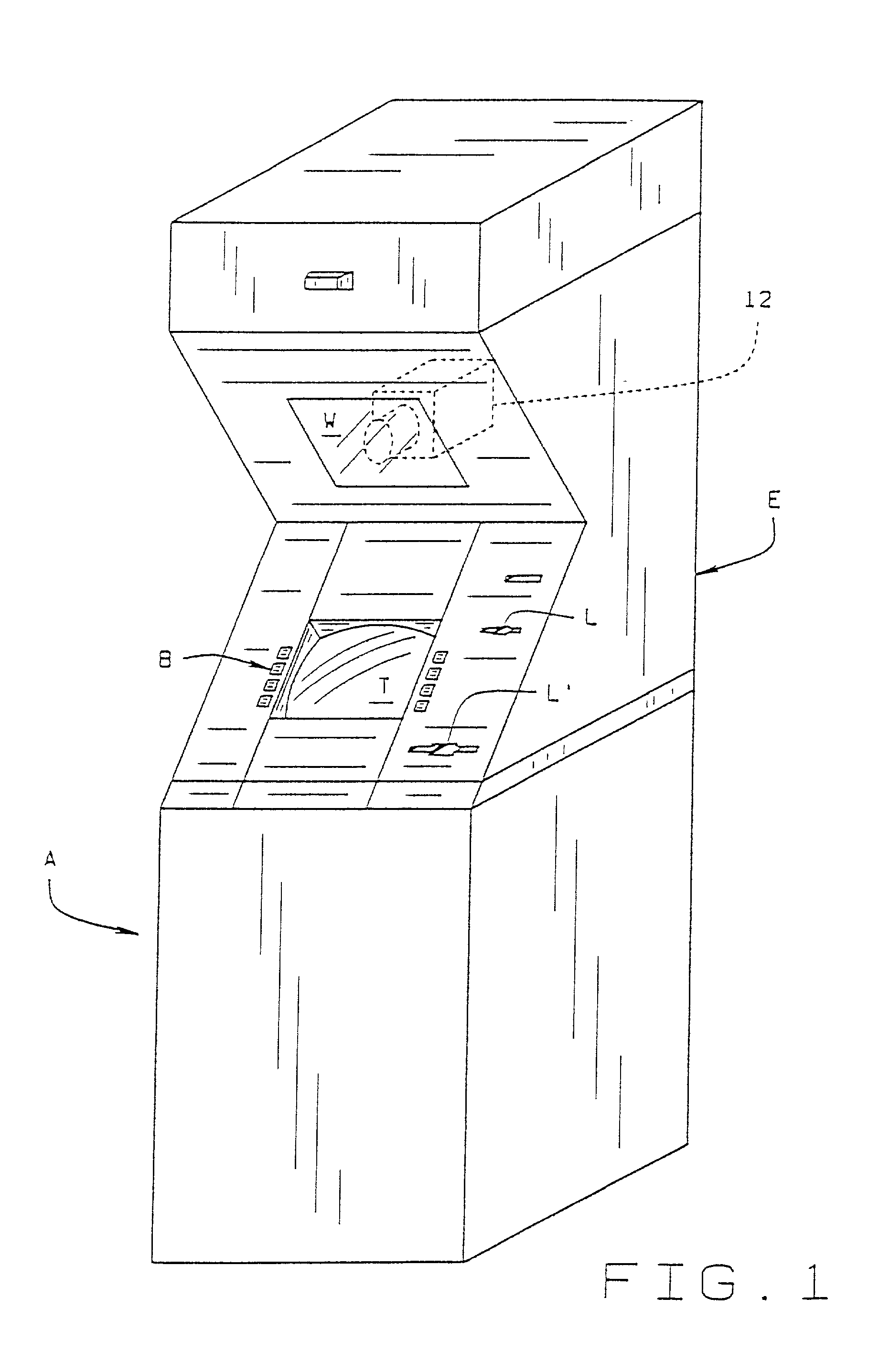
[0039]Referring to the drawings, a conventional monitoring system S utilizes a camera C which views a scene of interest. In security systems, this could be the interior of a bank, an Automatic Teller Machine (ATM), the counter of a fast food store, etc. Video images produced by the camera are transmitted to recorder R which can be on the premises or remotely located. The images are recorded on a magnetic tape M or the like. When the tape is full, it is rewound and recorded over; or it is stored away and replaced with a new tape. If something of consequence occurs, in order to view it, the tape is transferred to a playback unit P where it is rewound to the beginning. The tape is then scanned to the point where recordation of the occurrence commences for viewing by interested parties. As noted, if the tape is simply recorded on over and over, the recorded image is degraded and vital information may be lost or rendered incomprehensible.

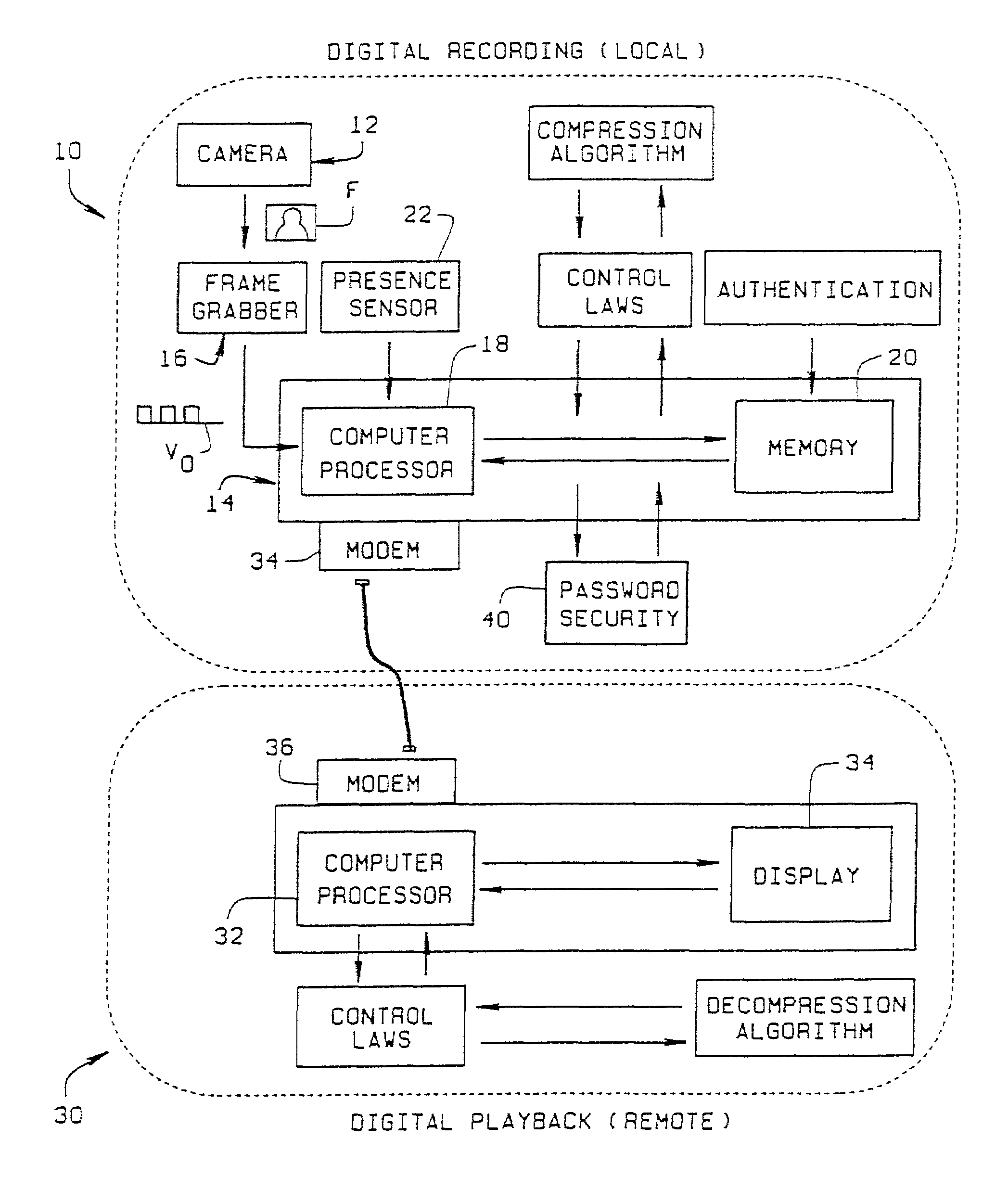
[0040]As shown in FIG. 3, a digital video recordin...


PUM


Abstract

A digital video recording system (10) includes a video camera (12) directed at a scene of interest to continuously view the scene and generate video images (F) of the scene. An image processor (14) is configured to compare the video image (F) with a previously established reference image (Fr) of the scene to determine if changes have occurred. The image processor includes a memory (20) in which portions of video images (F) are stored, together with the time and date information as to when the image was acquired. A video playback capability (30) allows the memory to be accessed to retrieve the portions of the video images for image reconstruction. The playback system enables the memory to be accessed at any desired date and time location so an image of interest can be reconstructed without having to scan stored video images in a date/time sequence. Accessing the memory is done without interrupting the image processor's processing of currently acquired video images.

Description

CROSS-REFERENCE TO RELATED APPLICATIONS[0001]This application is a continuation-in-part application, based upon U.S. patent application Ser. No. 09 / 356,129, filed on Jul. 17, 1999, now U.S. Pat. No. 6,317,152 from which priority is claimed.STATEMENT REGARDING FEDERALLY SPONSORED RESEARCH OR DEVELOPMENT[0002]Not applicable.BACKGROUND OF THE INVENTION[0003]This invention relates to video recording, and more particularly, to a digital video recording system for use at Point of Sale (POS) locations, Automated Teller Machines (ATM's), and other locations where the monitoring of activities is important.[0004]Video recording equipment is in common use throughout industry and commerce. Conventional video recording systems are analog systems employing a video recorder which records images on a magnetic tape. The recorder used is a slow scan recorder whose video input is provided by a camera located at the POS or ATM. Recording is typically continuous over a predetermined period which is typi...

Claims


Application Information

Patent Timeline
IPC IPC(8): H04N7/12H04B1/66H04N5/77H04N5/775H04N5/781H04N5/92H04N7/18
CPCG07F19/20G07F19/207H04N5/772H04N7/183H04N5/77H04N5/775H04N5/781H04N5/9205
Inventor HOBSON, GREGORY L.MOORE, JERRYWOOTTON, JOHN R.MYERS, JAMES C.ORTH, JEFFREY J.
Owner ADT SERVICES
Why Eureka
Try Eureka