
Modulation control

Inactive Publication Date: 2006-10-03
LUMENTUM TECH UK LTD
View PDF12 Cites 66 Cited by
  • Summary
  • Abstract
  • Description
  • Claims
  • Application Information

AI Technical Summary

Benefits of technology

[0015]The arrangement according to the invention advantageously controls the operating point of the modulators and phase shifter of the quadrature PSK

Problems solved by technology

With ongoing developments in optically amplified dense wavelength division multiplex (DWDM) optical links as the backbone of point-to-point information transmission and the simultaneous increase in bit rate applied to each wavelength and the simultaneous increase in the number of channels, the finite width of the erbium gain window of conventional erbium-doped optical amplifiers (EDFAs) could become a significant obstacle to further increases in capacity.
In WDM several factors limit the minimum channel spacing for binary amplitude signalling, and in practice spectral efficiency is limited to ˜0.3 bit / s / Hz.
Although increasing the per-channel bit rate tends to reduce system equipment, there are several problems that need to be overcome for transmission at bit rates above 10 Gbit / s; these being:dispersion management of the optical fibre links, this becomes increasingly difficult with increased bit rate;Polarisation mode dispersion (PMD) in the optical fibre causes increased signal degradation;Realisation of electronic components for multiplexing, de-multiplexing and modulator driving becomes increasingly difficult.
A particular disadvantage of QPSK is that demodulation requires, at the demodulator, a local laser which is optically phase-locked to the transmitter laser.
It further requires adaptive polarisation control which, in conjunction with a phase recovery system, represents a very high degree of complexity.
Furthermore, systems that require a coherent local laser are sensitive to cross-phase modulation (XPM) in the optical fibre induced by the optical Kerr non-linearity, which severely restricts the application to high capacity DWDM transmission.
Although DBPSK does not require a phase-locked laser at the receiver it does not provide any significant advantages compared to conventional amplitude NRZ signalling.

Method used


Image

  • Modulation control
  • Modulation control

Examples


Embodiment Construction

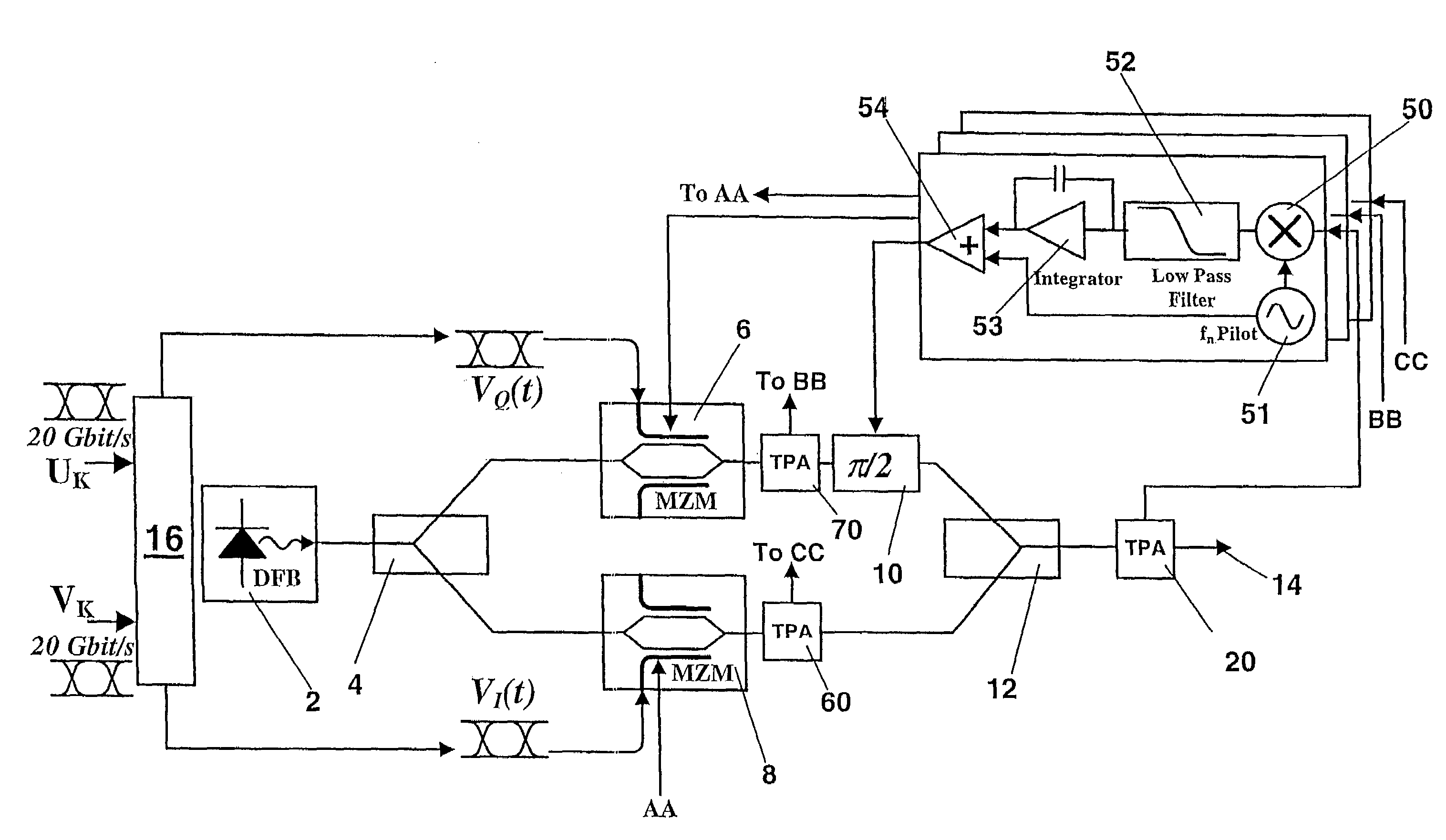
[0019]FIG. 1 shows an optical phase shift key modulator arrangement for encoding two 20 Gbit / s NRZ data streams Uk, Vk onto a single optical carrier. Typically the modulator arrangement would be used as part of a transmitter in a WDM optical communications system with a respective modulator arrangement for each WDM wavelength channel.

[0020]The modulator arrangement comprises a single frequency laser 2, for example a distributed feedback (DFB) semiconductor laser due to its stable optical output for a given wavelength, which is operated to produce an unmodulated optical output of a selected wavelength, typically a WDM wavelength channel.

[0021]Light from the laser is transmitted to the integrated photonic device, where it is divided by an optical splitter 4 into two parts and each part is applied to a respective phase modulator 6, 8. Each phase modulator 6, 8 is configured such that it selectively modulates the phase by 0 or π radians in dependence upon a respective binary (bipolar) N...


PUM


Abstract

A modulator arrangement for modulating an optical signal using a quadrature phase shift key for use in an optical wavelength division multiplex (WDM) optical communications system comprising a laser (2) for producing an optical signal of a selected wavelength, which signal is split by a splitter (4), each part of said split signal being applied to a respective phase modulator (6, 8) each for which phase modulators is adapted to modulate the phase of the signal in dependence on a respective drive voltages. The phase of the output of at least one modulator (6) is shiftable at least in part by a phase shifter (10), the split signals being recombined by an optical recombiner (12) to form an optical phase shift key output, wherein the output power is monitored by a detector (20), the detector signal then being used to drive a feedback arrangement to control electrodes of the phase modulators (6, 8) and / or phase shifter (10).

Description

RELATED APPLICATIONS[0001]This application is a 35 U.S.C. 371 national stage filing of International Application No. PCT / GB02 / 05395, filed 29 Nov. 2002, which claims priority to Great Britain Patent Application No. 0128784.6 filed on 30 Nov. 2001, in Great Britain. The contents of the aforementioned applications are hereby incorporated by reference.BACKGROUND OF THE INVENTION[0002]The invention relates to a method and apparatus for controlling a quadrature phase shift key encoder in a wavelength division multiplex (WDM) optical communications system.[0003]In this specification the term “light” will be used in the sense that it is used generically in optical systems to mean not just visible light but also electromagnetic radiation having a wavelength between 800 nanometres (nm) and 3000 nm. Currently the principal optical communication wavelength bands are centred on 1300 nm, 1550 nm (C-Band) and 1590 nm (L-Band), with the latter bands receiving the majority of attention for commerci...

Claims


Application Information

Patent Timeline
IPC IPC(8): G02F1/03H04B10/50H04B10/556
CPCG02F1/0123H04B10/505H04B10/50575H04B10/50577H04B10/5561
Inventor GRIFFIN, ROBERT
Owner LUMENTUM TECH UK LTD
Learn More