Multi-field classification using enhanced masked matching

a multi-field classification and enhanced masking technology, applied in the field of bit pattern matching, can solve the problems of high cost of supporting a large rule set, unsuitable high-speed implementation approach, and ambiguity

Inactive Publication Date: 2006-10-03
MICROSEMI STORAGE SOLUTIONS
View PDF5 Cites 56 Cited by
  • Summary
  • Abstract
  • Description
  • Claims
  • Application Information

AI Technical Summary
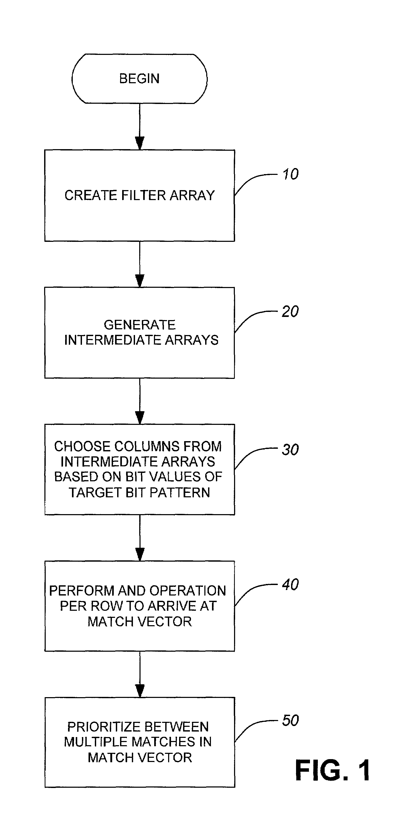
Problems solved by technology

The grammatical / lexical parser provides flexible solutions to this problem, but the cost of supporting a large rule set is high.
Ambiguity arises when multiple regions overlap each other.
While this approach is simple and efficient in use of memory (memory size grows linearly as the size of the rule set increase), this approach is unsuitable for high-speed implementation.
But it is not easy to extend the concept to more fields.
The grid of tries approach requires intensive precompute time.
This approach has the weakness of not supporting “conflict” between patterns (as stated in line 21˜26, column 22 of U.S. Pat. No. 5,995,971).
This weakness limits the use of the classification scheme.
Because of the computation complexity in the cross-producting operating, this scheme has a poor scaling property.
This scheme also requires a time consuming data structure generation process, hence the rule update speed is slow.
But the hardware cost (silicon area) and power consumption are high.
For these reasons, current available CAMs are typically small.
Since it relies on the policy database structure, in the worst case, little reduction can be achieve at each step.
In a normal case, the lookup performance gain is achieved at the cost of high memory size and very long precomputation time.
These factors directly affect chip feasibility if either factor is too large.
Some classification methods require a very long pre-processing time and / or intrusive reload of rule image data structure for a small change in the rule set.
The long update / pre-processing time prevents such methods from being effective for microflow classification for provision of differentiated / integrated QOS (Quality of Service) where the rule sets are often session dependent or require frequent updates with low latency tolerance.

Method used


Image

  • Multi-field classification using enhanced masked matching
  • Multi-field classification using enhanced masked matching
  • Multi-field classification using enhanced masked matching

Examples


Embodiment Construction

[0050]To clarify the terminology used in this description the following definitions are provided:

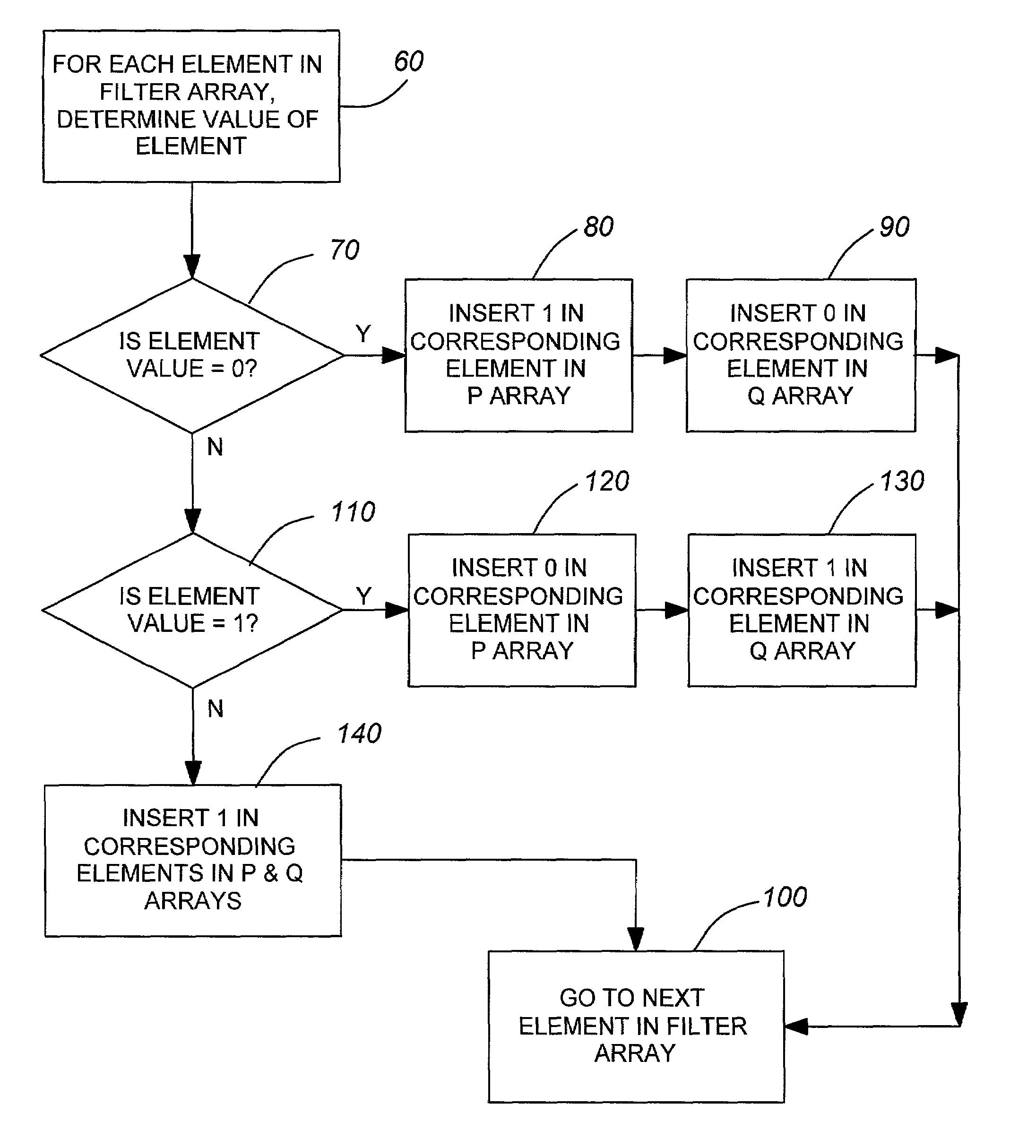
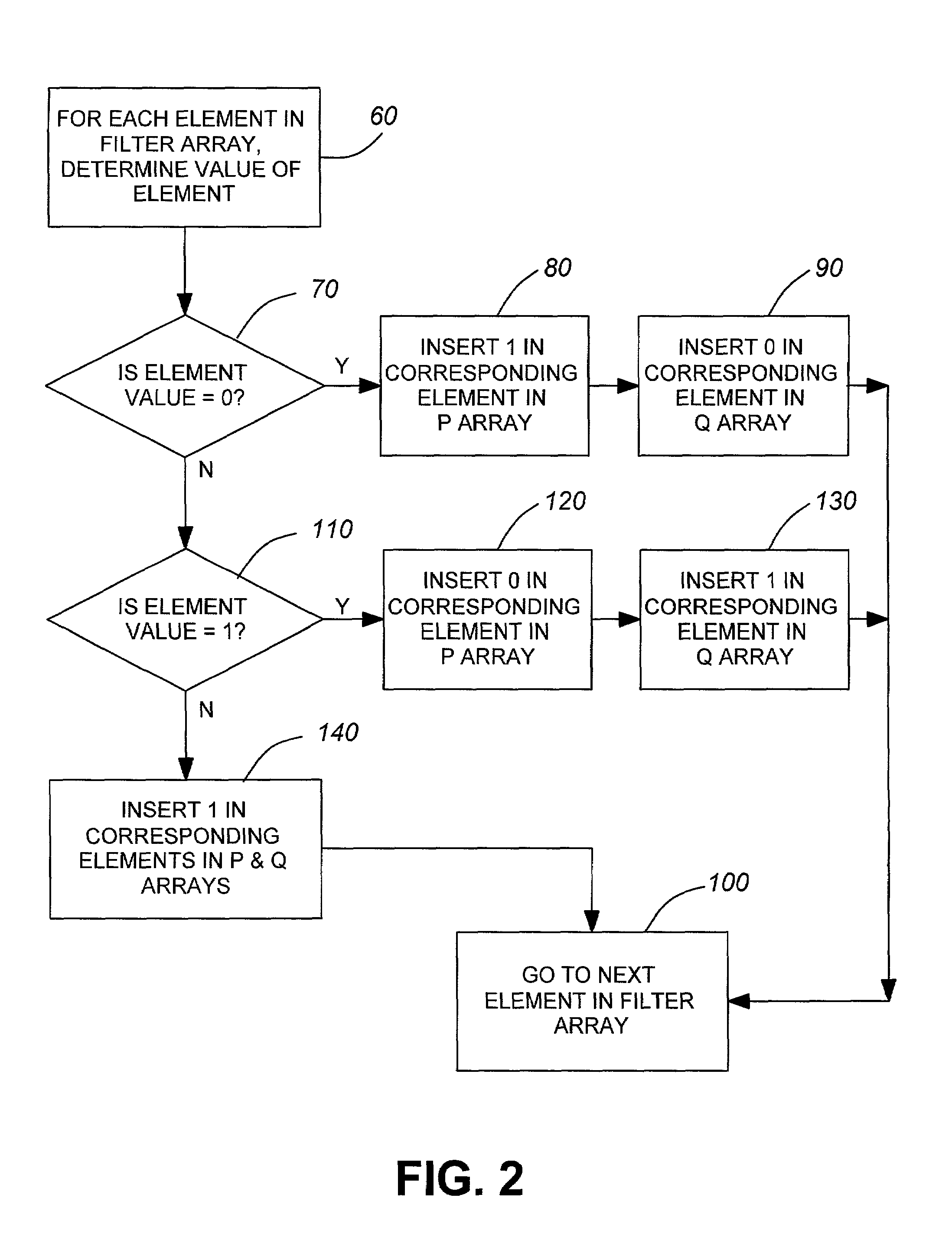
[0051]Filter: A filter defines a mask-matching rule. The method below assumes that a filter contains W bits and forms a concatenation of all the fields at which the classifier needs to look. A filter is further defined as a W-bit 3-value rule set. Each bit can take either ‘1’, ‘0’, or ‘x’, which means that the bit needs to be 1, 0, or don't-care (x) to match this filter. Each rule can also be termed a filter bit.

[0052]Rule Set: A rule set is a collection of N filter rules indexed from 1 to N. The rule set defines a single order of priority. A rule with larger index value has higher priority than a rule smaller index. The symbols F[0] . . . F[N−1 ] are used to represent filters 0 . . . N. A rule set can be represented by the 3-value matrix F[N,W], where F[i,j] means the mask matching value of rule i bit j.

[0053]Field Vector: The packet field data to be classified. It is W-bit 2-value vect...


PUM


Abstract

Methods and apparatus for finding a match between a target bit pattern and multiple filter bit patterns. A filter array is created from the filter bit patterns and at least one intermediate array is generated from the filter array. Specific columns of the intermediate arrays are then extracted based on bit values of the target bit pattern. A row by row AND operation is performed on these columns to arrive at a match vector. the match vector identifies which of the filter bit patterns in the filter array match the target bit pattern. The method is implemented by using multiple classifier elements operating in parallel with each classifier element handling multiple filter bit patterns.

Description

FIELD OF THE INVENTION[0001]The present invention relates to bit pattern matching. More specifically, the present invention relates to processes and devices for matching a target bit pattern with multiple filter bit patterns.BACKGROUND OF THE INVENTION[0002]In data networks, routers classify packets to determine the micro-flows the packets belong to and then apply the classification to the packets accordingly. Flow identification is the essential first step for providing any flow dependent service. A number of network services require packet classification including access-control, firewalls, policy-based routing, provision of integrated / differentiated qualities of service, traffic billing, secure tunnelling. In each application, the classifier determines which micro-flow an arriving packet belongs to so as to determine whether to forward or filter, where to forward it to, what class of service it should receive, the scheduling tag / state / parameter that it is associated with, or how ...

Claims


Application Information

Patent Timeline
Patent Type & Authority Patents(United States)
IPC IPC(8): H04L12/28G06F7/00H04L12/56H04L29/06
CPCH04L45/00H04L45/54H04L63/0227H04L63/0263H04L63/101Y10S707/99933
Inventor LIAO, HENG
Owner MICROSEMI STORAGE SOLUTIONS
Why Eureka
Try Eureka