Synchronized controlled oscillation modulator

a technology of oscillator and synchronization control, which is applied in the direction of pulse technique, process and machine control, instruments, etc., can solve the problems of limiting system bandwidth, complicated design, and difficult stable and robust control system design, and achieve the effect of superior modulation

Inactive Publication Date: 2006-10-10
BANG & OLUFSEN ICEPOWER
View PDF10 Cites 31 Cited by
  • Summary
  • Abstract
  • Description
  • Claims
  • Application Information

AI Technical Summary

Benefits of technology

[0011]The invention provides significant advantages in performance, topological simplification, improved robustness, stability and efficiency compared to prior art.
[0016]According to this embodiment, pulse modulation in general power conversion systems is provided that implements multiple level pulse modulated signals—hence reducing the output switching noise energy and enhancing the possibilities for control system implementation.

Problems solved by technology

This limits the system bandwidth and complicates design.
Also, a stable and robust control system design is difficult.
A problem with this technique is that it can only synthesize standard two level modulation—hence giving disadvantages concerning the efficiency of the amplifier.
Another problem arises in multi channel systems such as multi channel audio amplifiers, the oscillating modulators will have oscillation frequency variations, which will cause intermodulation products, adding distortion components within the audio bandwidth.
Furthermore the system can only synchronize a modulator to an external clock leading to higher complexity when implementing an external clock generator.

Method used


Image

  • Synchronized controlled oscillation modulator
  • Synchronized controlled oscillation modulator
  • Synchronized controlled oscillation modulator

Examples


Embodiment Construction

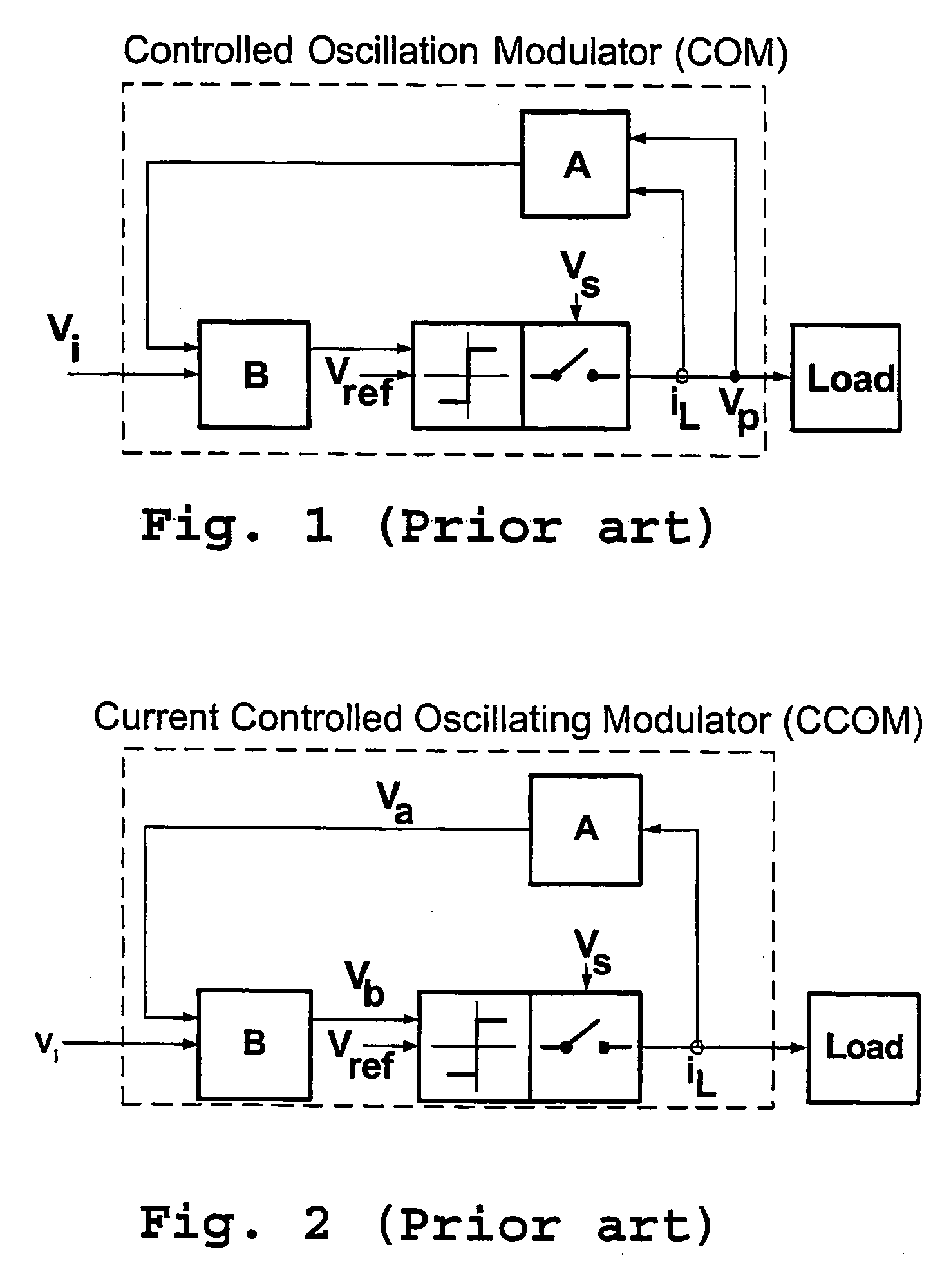
[0033]In the following detailed description of the preferred embodiments, the COM modulators can be Voltage Controlled Oscillating Modulators (FIG. 1) as described in U.S. Pat. No. 6,297,692 or Current controlled Oscillating Modulators (FIG. 2) as described in the International Publication Number WO 02 / 025357, both hereby incorporated by reference.

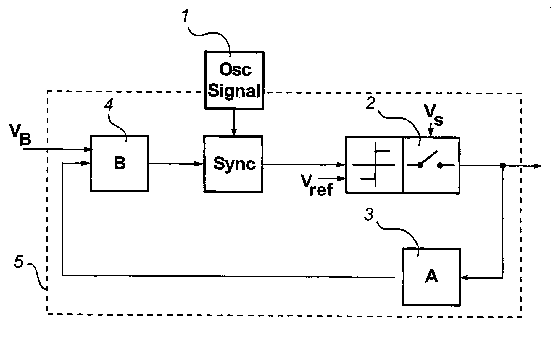
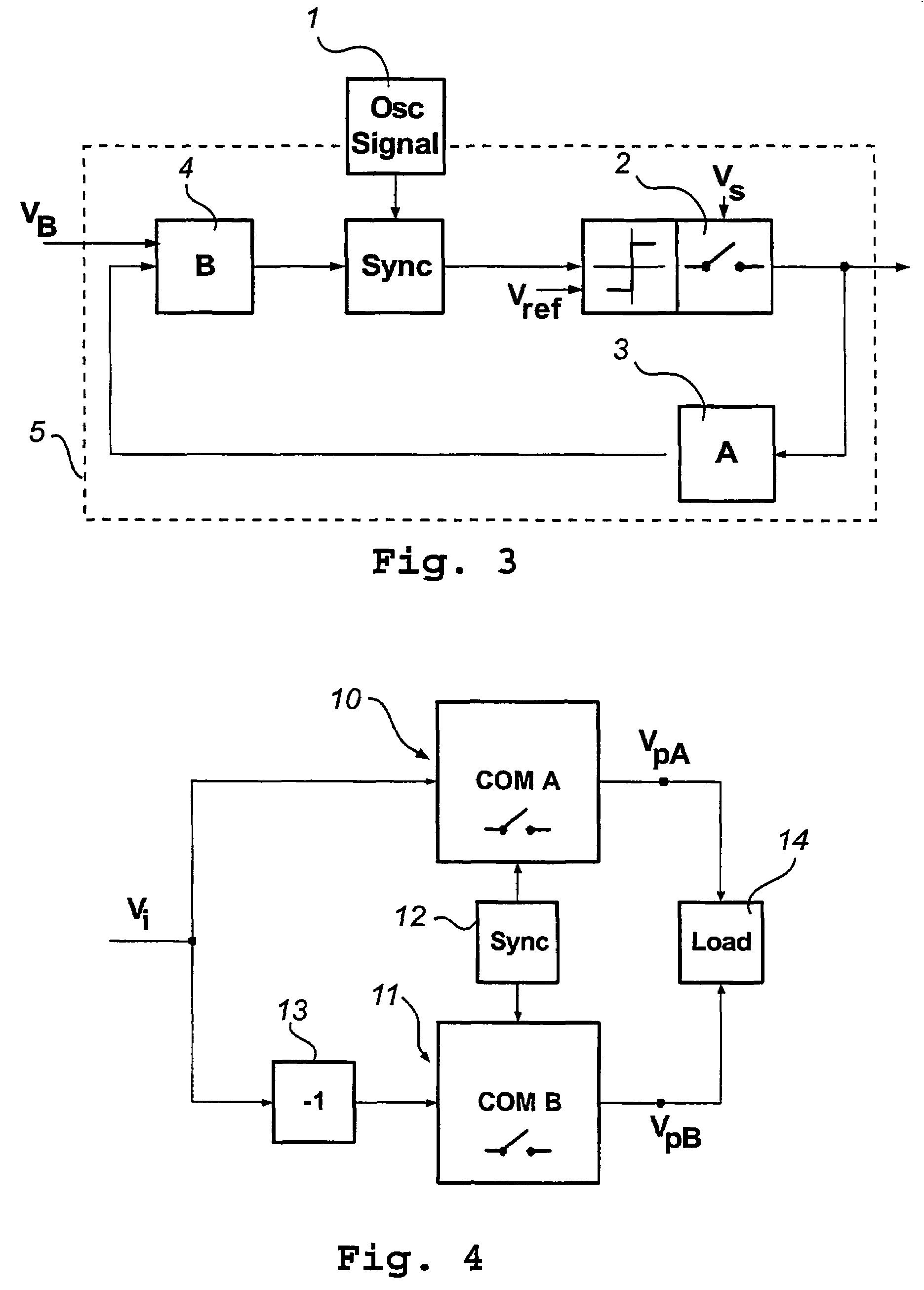
[0034]A power conversion system comprising a modulator according to a first preferred embodiment of the invention is shown in FIG. 3. The system comprises a power stage 2, a control system with a feedback block 3 and a forward block 4. The power stage 2 can comprise one or a plurality of half-bridges, preferably a full-bridge comprising two half-bridges. The feedback block and the forward block constitute an oscillating modulator 5. An external signal source 1, also referred to as an oscillating signal generator block, is connected to a synchronization block 6 in the modulator 5.

[0035]The synchronization of the modulator 5 is obtained by a...


PUM


Abstract

A synchronized controlled oscillation modulator (SCOM), comprising at least one, Controlled Oscillation Modulator (5), and synchronizing means (1, 6) connected to said COM modulator. The modulator can comprise several COM modulators, and the synchronizing means can be arranged between the COM systems, so that the oscillation modulator signal is used as synchronization signal. The invention provides significant advantages in performance, topological simplification, improved robustness, stability and efficiency compared to prior art.

Description

TECHNICAL FIELD[0001]This invention relates to a self-oscillating modulator, comprising a comparator and a power amplification stage for pulse width modulation, and higher order oscillating loops comprising first feedback means and first forward means securing stable oscillating conditions.[0002]The invention also relates to a switching power conversion system, such as DC-AC (e.g. audio amplification), DC-DC or AC-AC conversion systems or any combination of the above mentioned comprising such a modulator. The invention may advantageously be used for improved power conversion in any system, in particular precision DC-AC conversion systems such as high efficiency audio amplification.TECHNICAL BACKGROUND[0003]The pulse width modulator is a central element of any power conversion system. Most switching power converters are based on Pulse Width Modulation (PWM) as means to control efficient conversion between domains (DC or AC).[0004]A typical power converter may include a PWM modulator,...

Claims


Application Information

Patent Timeline
Patent Type & Authority Patents(United States)
IPC IPC(8): H03K7/00H03F3/38H02M3/158
CPCH02M3/1584H03F3/217H03F2200/351H03F3/38
Inventor NIELSEN, KARSTENHANSEN, JESPER LIND
Owner BANG & OLUFSEN ICEPOWER
Why Eureka
Try Eureka