
Parallel architecture for graphics primitive decomposition

Inactive Publication Date: 2006-10-10
S3 GRAPHICS
View PDF14 Cites 59 Cited by
  • Summary
  • Abstract
  • Description
  • Claims
  • Application Information

AI Technical Summary

Benefits of technology

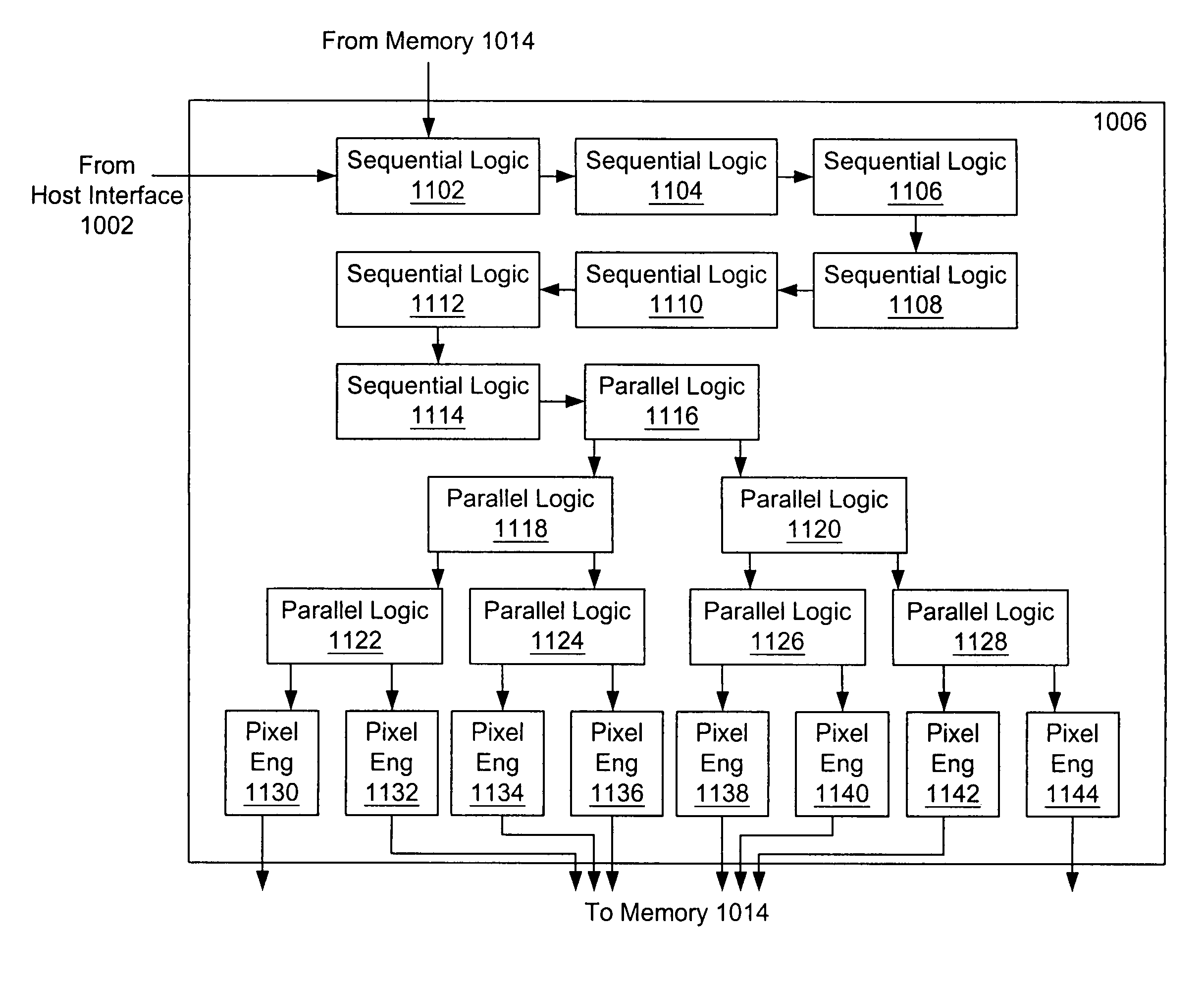
[0027]The present invention advantageously provides a system and method that allows graphic primitives to be efficiently decomposed. In one embodiment, a graphics engine includes a predetermined number of sequential logic circuits and parallel logic circuits connected together to form a pipeline structure. This pipeline structure receives information related to polygonal portions of a raster image from memory and information related to primitives from a source. The pipeline structure subsequently determines whether a polygonal portion of the raster image is at least partially inside the primitive. If the polygonal portion is partly inside, the pipeline structure divides the polygonal portion into a predetermined number of polygonal subportions.

Problems solved by technology

In addition to requiring an extra accumulator register, arithmetic division calculations are generally slow.
As such, rasterizing using the “edge and span traversal” technique is not the most efficient approach.
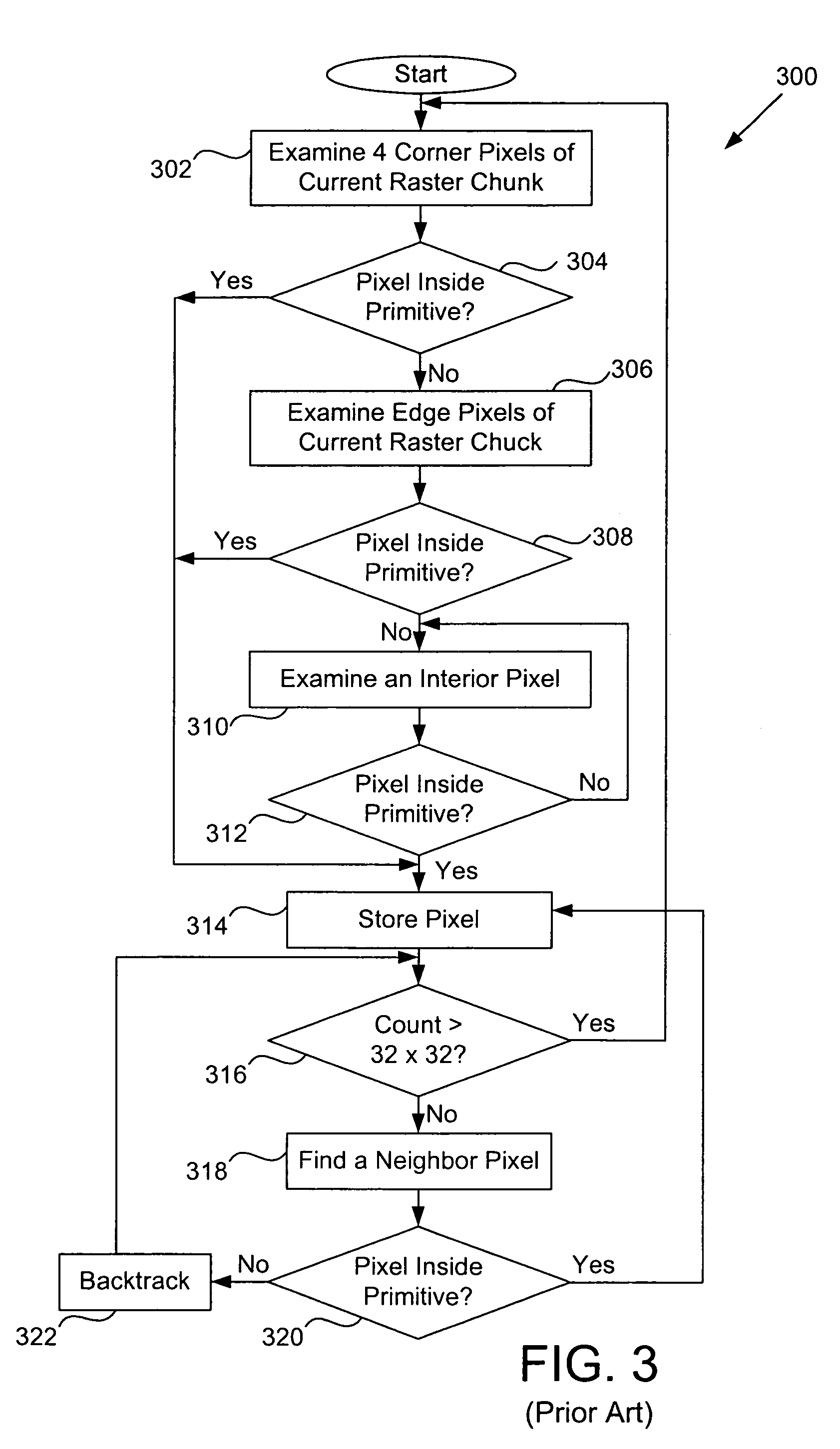
Such searching may be intermittently interrupted for backtracking as a result of straying outside the primitive.
Thus, this conventional implementation is rather ad-hoc and may not be effective.
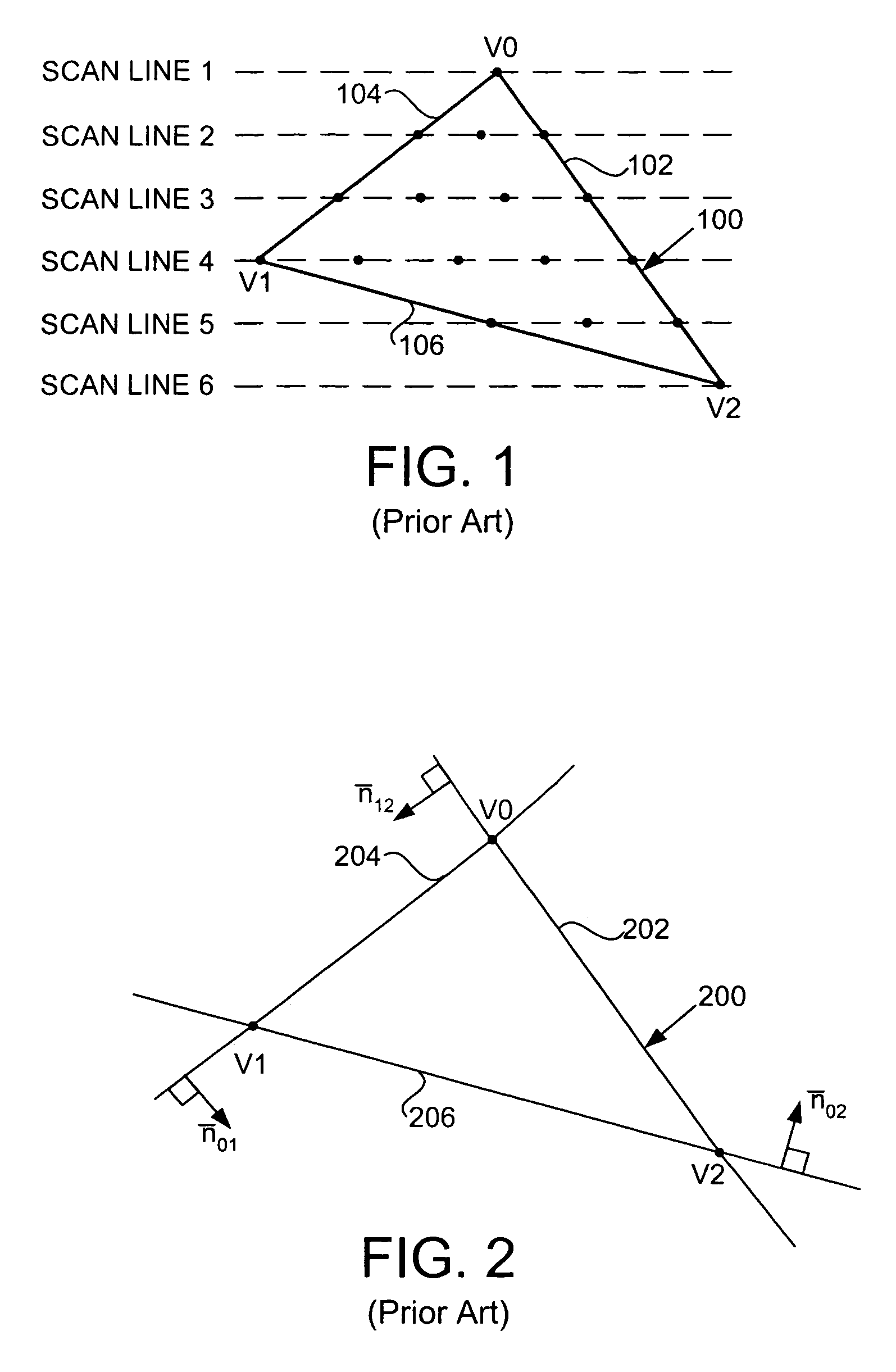
Moreover, because the conventional approach is inherently sequential (i.e., one pixel is examined at a time), it is not the most efficient technique given the large number of pixels in each chunk.

Method used


Image

  • Parallel architecture for graphics primitive decomposition
  • Parallel architecture for graphics primitive decomposition
  • Parallel architecture for graphics primitive decomposition

Examples


Embodiment Construction

[0042]FIG. 4 is a block diagram of a computer system 400 for implementing the present system and method. The computer system 400 includes a central processing unit (CPU) 402, a system memory 404, and a graphics controller 406, all of which are coupled to a system bus 408. The system bus 408 may be any one of a number of different types of host or input / output (I / O) buses, including industry standard architecture (ISA), extended ISA (EISA), peripheral component interconnect (PCI), video electronic standard association (VESA) local bus, or any other standardized computer system bus. The system bus 408 may also be an accelerated graphics port (AGP).

[0043]The system memory 404 stores information, instructions, and software programs such as an application program, a graphics subroutine package and an operating system executable by the CPU 402. The application program may be used to construct two and three-dimensional graphics images and models. These images and modules are data structure...


PUM


Abstract

A parallel architecture for determining pixels inside a graphics primitive is provided. The architecture is a pipeline structure having a predetermined number of sequential logic circuits connected in series followed by a predetermined number of parallel logic circuits arranged in a pyramid structure. Each sequential logic circuit uses arithmetic edge functions corresponding to edges of a graphics primitive to determine whether a polygonal portion of a raster image is inside the graphics primitive. If the polygonal portion is at least partly inside the graphics primitive, the sequential logic circuit divides the polygonal portion into a predetermined number of subportions and computes descriptors (e.g., vertices and translated edge functions) for each subportion sequentially. Descriptors are then transferred sequentially to the next stage. Each parallel logic circuit performs the same functions as that of a sequential logic circuit except that a parallel logic circuit computes descriptors of the subportions in parallel and transfers them to the next stage in parallel.

Description

CROSS-REFERENCES TO RELATED APPLICATIONS[0001]This application claims the benefit of Provisional Patent Application Ser. No. 60 / 204,203, filed on May 15, 2000, entitled “Parallel Architecture for Graphics Primitives Decomposition,” which is incorporated herein by reference. The present application also is related to and incorporates by reference co-pending U.S. patent application Ser. No. 09 / 858,306, by Daniel H. McCabe, entitled “Graphics Primitive Decomposition Using Edge Functions and Recursive Tile Subdivision”, filed on May 15, 2001.BACKGROUND OF THE INVENTION[0002]1. Field of the Invention[0003]The present invention relates generally to computer graphics and more particularly to graphics primitive rasterization.[0004]2. Description of Related Art[0005]In graphic systems, graphic objects are typically constructed with combinations of graphics primitives in a geometrical model definition stage. Graphics primitives may include lines, characters, areas such as triangles and ellips...

Claims


Application Information

Patent Timeline
IPC IPC(8): G06T1/20G06T15/40
CPCG06T11/40
Inventor MCCABE, DANIEL H.
Owner S3 GRAPHICS
Learn More