Endoscopic imaging system making it possible to detachably attach expansion unit having external expansion facility and add expansion facility for improving capability of system

Inactive Publication Date: 2006-10-10
OLYMPUS CORP
View PDF17 Cites 53 Cited by
  • Summary
  • Abstract
  • Description
  • Claims
  • Application Information

AI Technical Summary

Benefits of technology

[0014]An aspect of the present invention is to provide an endoscopic imaging system making it possible to detachably attach an expansion

Problems solved by technology

This may lead to a complex system configuration and time-consuming handling and invite an increase in cost.
This poses a problem of poor use efficiency of the recording medium.
However, since a level of compressibility must be changed to another at every endoscopic examination, there arises a problem that handling becomes a nuisance.
Another problem is that this feature is unacceptable at a medical site at which it is hard to touch the system.
If a certain level of compressibility is always used for compression, image data may be recorded at an unnecessarily low level of compressibility.
This poses a problem that the use efficiency of a recording medium deteriorates.
Ther

Method used


Image

  • Endoscopic imaging system making it possible to detachably attach expansion unit having external expansion facility and add expansion facility for improving capability of system
  • Endoscopic imaging system making it possible to detachably attach expansion unit having external expansion facility and add expansion facility for improving capability of system
  • Endoscopic imaging system making it possible to detachably attach expansion unit having external expansion facility and add expansion facility for improving capability of system

Examples


first embodiment

[0078]

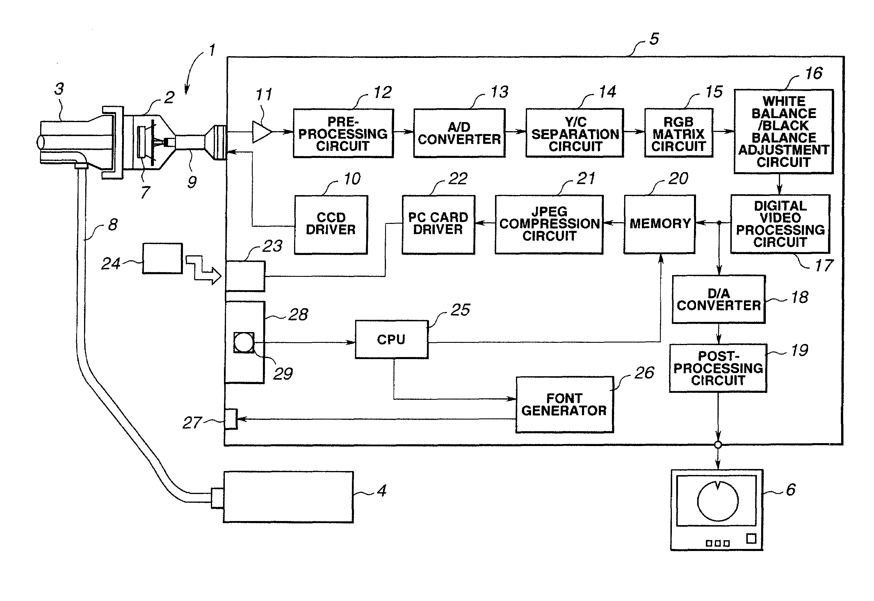
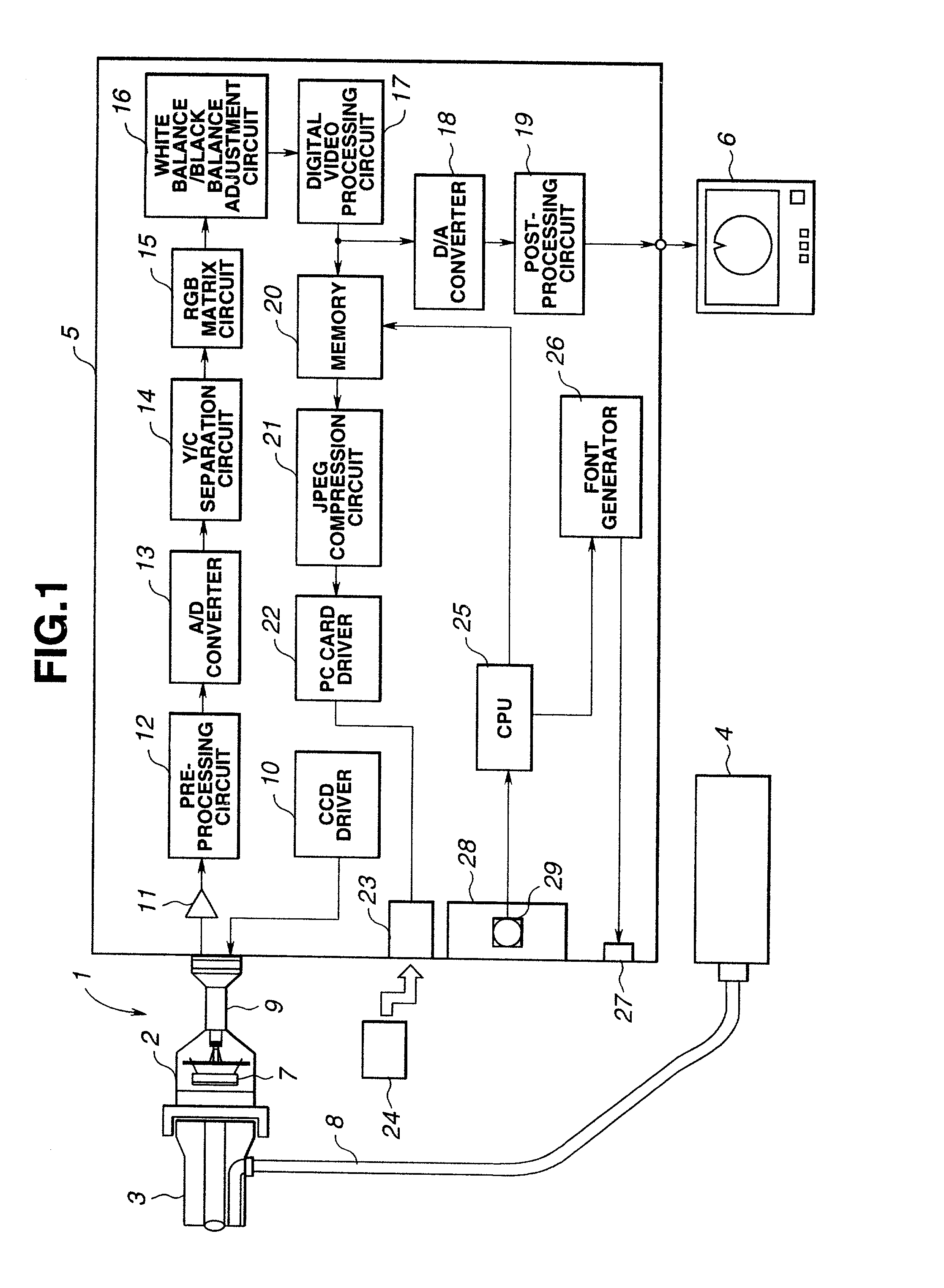
[0079]As shown in FIG. 1, an endoscopic imaging system 1 of this embodiment comprises a camera head 2 having an imaging means incorporated therein, a scope 3 connected to the camera head 2, a light source apparatus 4 for supplying illumination light to the scope 3, a camera control unit 5 (hereinafter a CCU) serving as a main processor unit for processing a signal sent from the imaging means incorporated in the camera head 2, and a TV monitor 6 for displaying a standard video signal processed by the CCU 5. The scope 3 is a rigid endoscope such as a laparoscope used for, for example, a surgical procedure in the field of surgery.

[0080]When the endoscope imaging system 1 is in use, a light guide 8 of the scope 3 is, as shown in FIG. 1, linked to the light source apparatus 4. Illumination light emanating from a lamp in the light source apparatus 4 passes through a diaphragm that is not shown, is converged by a lens, and falls on the opposing end surface of the light guide 8. The i...

second embodiment

[0099

[0100]The conventional system does not have an anti-liquid invasion structure formed around an expansion slot. When liquid 38 such as water is split over a CCU 37 as shown in FIG. 45, the liquid invades into the interior of an expansion slot 39 in which an expansion unit 40 is mounted. This may invite a short circuit between electrical contacts or corrosion in the CCU.

[0101]For improving the safety of medical equipment including a CCU with an expansion slot, the expansion slot is provided with an anti-liquid invasion means. An example of a structure including the anti-liquid invasion means will be described as another embodiment.

[0102]FIGS. 4 and 5 show a structure of an expansion slot in accordance with a second embodiment of the present invention. FIG. 4 is a front view and FIG. 5 is a sectional view.

[0103]An eaves-like projection 42 is formed on the upper margin of the opening of an expansion slot 41 formed in the face or lateral side of a CCU 5 over a range wider than the w...

third embodiment

[0105]

[0106]In a third embodiment, as shown in FIG. 6, a slope 44 is formed as part of an inner lower surface of an expansion slit 41 near the opening of the expansion slot. Owing to the slope 44, invasion of liquid into the expansion slot can be prevented as indicated with an arrow 43. Moreover, in a variant shown in FIG. 7, the whole expansion slot 41 may be formed on a slope 45. The same operation and advantage as those mentioned above can still be exerted.

[0107]According to the third embodiment, another member such as an eaves-like projection need not be formed.

[0108]As with the second embodiment, invasion of liquid into the expansion slot can be prevented with a simple structure.


PUM


Abstract

In an endoscopic imaging system, a signal representing an object image produced by a scope and projected by a camera head is processed by a CCU and displayed as an endoscopic image on a TV monitor. The object image is stored as digital image data on a memory in the CCU, read as image data of a still image, and recorded on a PC card mounted in a PC card slot. The PC card slot is formed in the front panel or the like of the CCU. A lid member or the like functioning as an anti-liquid invasion member and shield can be located at an opening of the slot.

Description

[0001]This application is a divisional application of Ser. No. 09 / 120,559, filed Jul. 22, 1998. Priority is claimed under 35 U.S.C. §119 based on Japanese Application Nos. H9-197114, filed Jul. 23, 1997; H9-201565 filed Jul. 28, 1997; H9-206679, filed Jul. 31, 1997 and H9-208123, filed Aug. 1, 1997.BACKGROUND OF THE INVENTION[0002]1. Field of the Invention[0003]The present invention relates to an endoscopic imaging system in which a view image produced by an endoscope is projected.[0004]2. Description of the Related Art[0005]Endoscopes having elongated insertion units thereof inserted into body cavities or the like and thus assisting in observation of object regions, various kinds of examinations, and cures and treatments have been widely adopted in the past. Assume that an optical endoscope such as a rigid scope or fiberscope is employed. In this case, generally, a camera head included in an endoscopic imaging system is attached to an eyepiece unit of the endoscope, and an endoscop...

Claims


Application Information

Patent Timeline
IPC IPC(8): H04N7/18H04N11/02A61B1/045A61B1/313H04N1/00H04N5/225
CPCA61B1/00022A61B1/00039A61B1/00055A61B1/00105A61B1/045H04N1/00127H04N7/183A61B1/307A61B1/3132A61B1/317A61B2560/0276A61B2560/0475H04N1/00286H04N2005/2255A61B1/00042H04N23/555
Inventor SAITO, KATSUYUKIMOCHIDA, AKIHIKOOGASAWARA, KOTAROKUSAMURA, NOBORUTSUNAKAWA, MAKOTOTASHIRO, HIDEKIYAMASHITA, SHINJIMATSUMOTO, KANICHIOHNO, WATARUHAGIHARA, MASAHIRONAKATSUCHI, KAZUTAKAKAMI, KUNIAKI
Owner OLYMPUS CORP
Why Eureka
Try Eureka