
Multi-layer and multi-direction fan device

a fan device and multi-direction technology, applied in the direction of insulated conductors, semiconductor/solid-state device details, cables, etc., can solve the problems of large electrical energy consumption, complicated circuit layout, and very delicate design of current integrated circuits, so as to prolong the life of the system and facilitate the layout of the system

Inactive Publication Date: 2006-10-17
QUANTA COMPUTER INC
View PDF14 Cites 15 Cited by
  • Summary
  • Abstract
  • Description
  • Claims
  • Application Information

AI Technical Summary

Benefits of technology

The multi-layer and multi-direction fan device effectively lowers the temperature of electronic systems, prolonging their lifespan by providing diversified heat dissipation through multiple wind outlets, enabling simultaneous cooling of CPUs and chip sets within limited spaces.

Problems solved by technology

With the great advancement of integrated circuit processes and the increasingly rising demand for higher integrated circuit capacities, the designs of current integrated circuits are very delicate and complex.
Both users and software applications place great demands on central processing units (CPU), thereby necessitating powerful but complex circuit layouts.
Although these central processing units provide many powerful functions, the complicated circuit design causes a great consumption of electrical energy.
This energy consumption results in raising the chip temperature, and in turn degrades performance and may cause permanent chip damage.
This problem is especially serious in portable electronic devices.
When heat cannot be dissipated instantly but instead accumulates within an electronic device, the device cannot function properly; and if, for example a CPU does not function properly, the whole computer is accordingly degraded and may even become irreparably damaged.

Method used


Image

  • Multi-layer and multi-direction fan device
  • Multi-layer and multi-direction fan device
  • Multi-layer and multi-direction fan device

Examples


Embodiment Construction

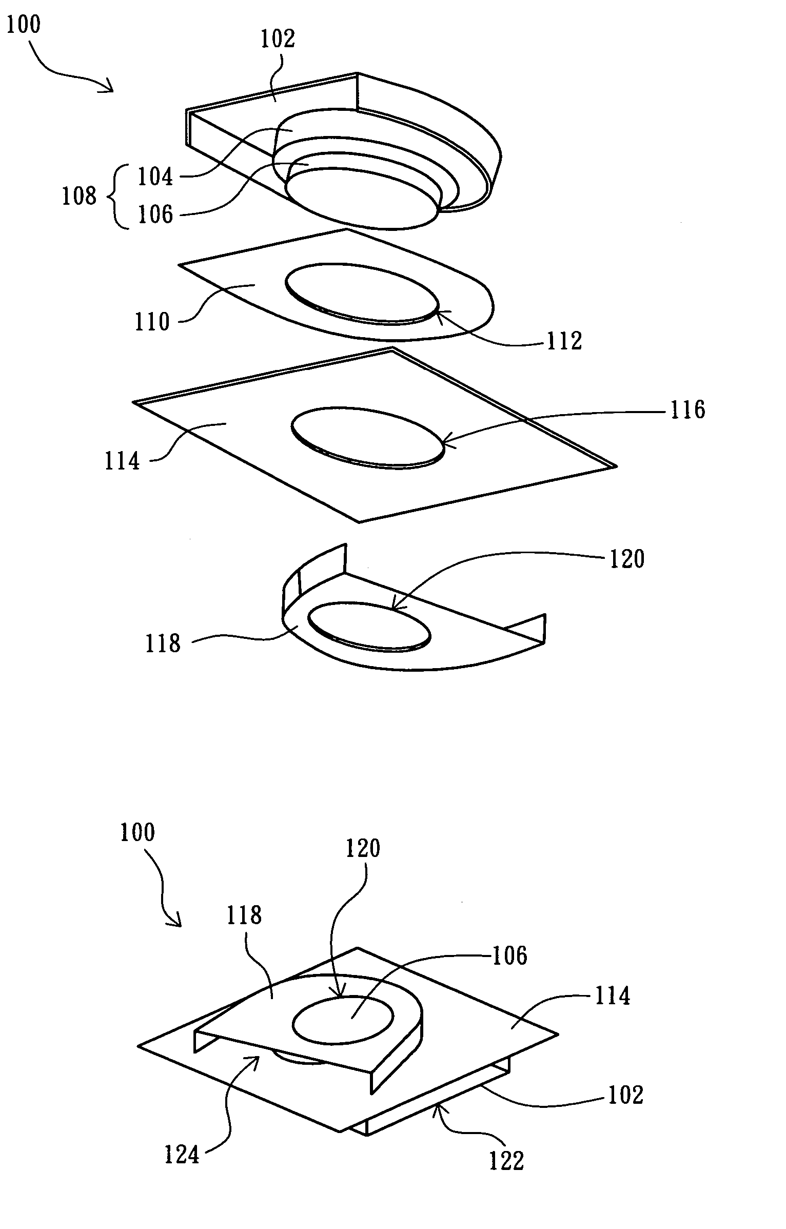
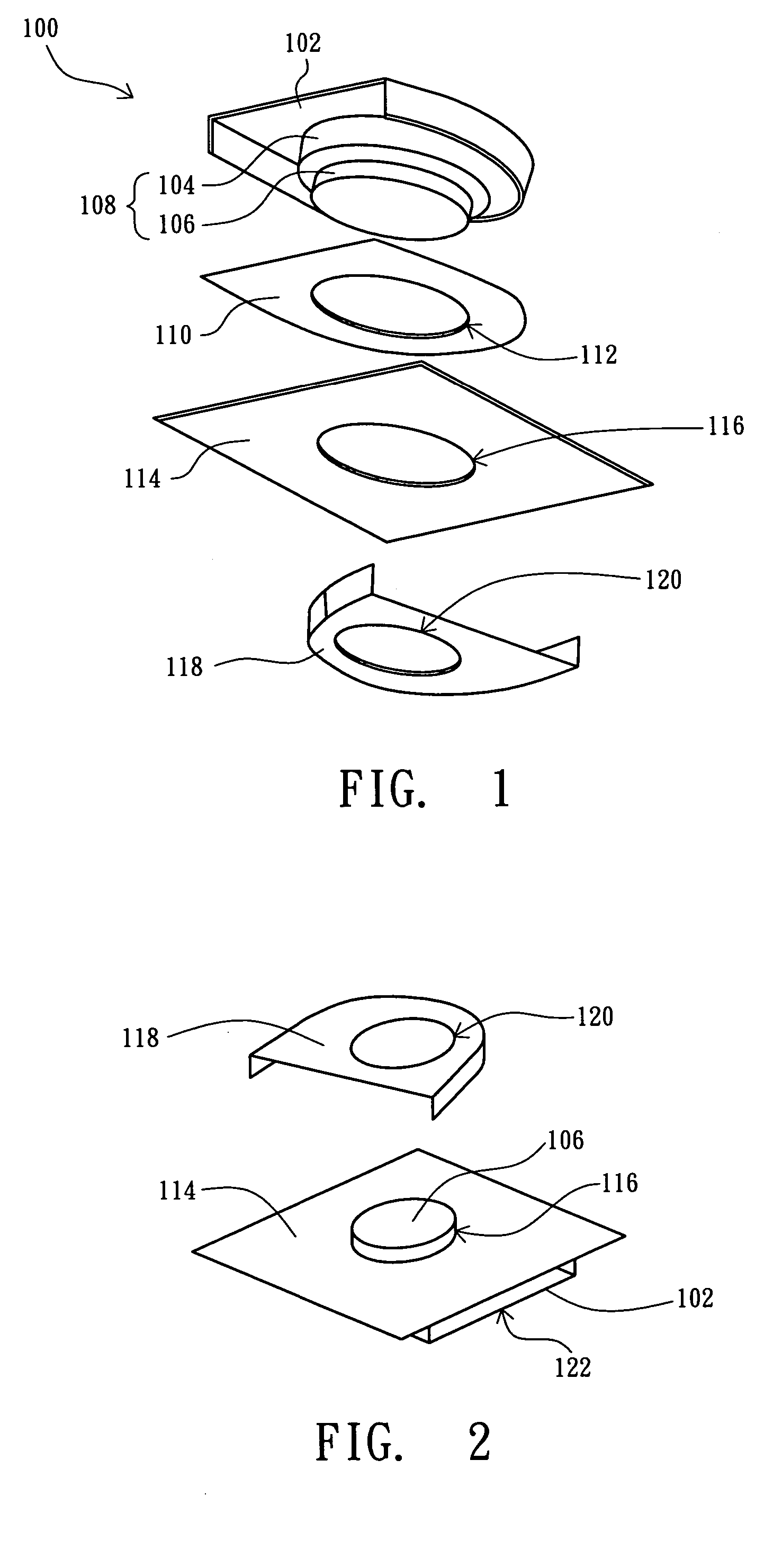
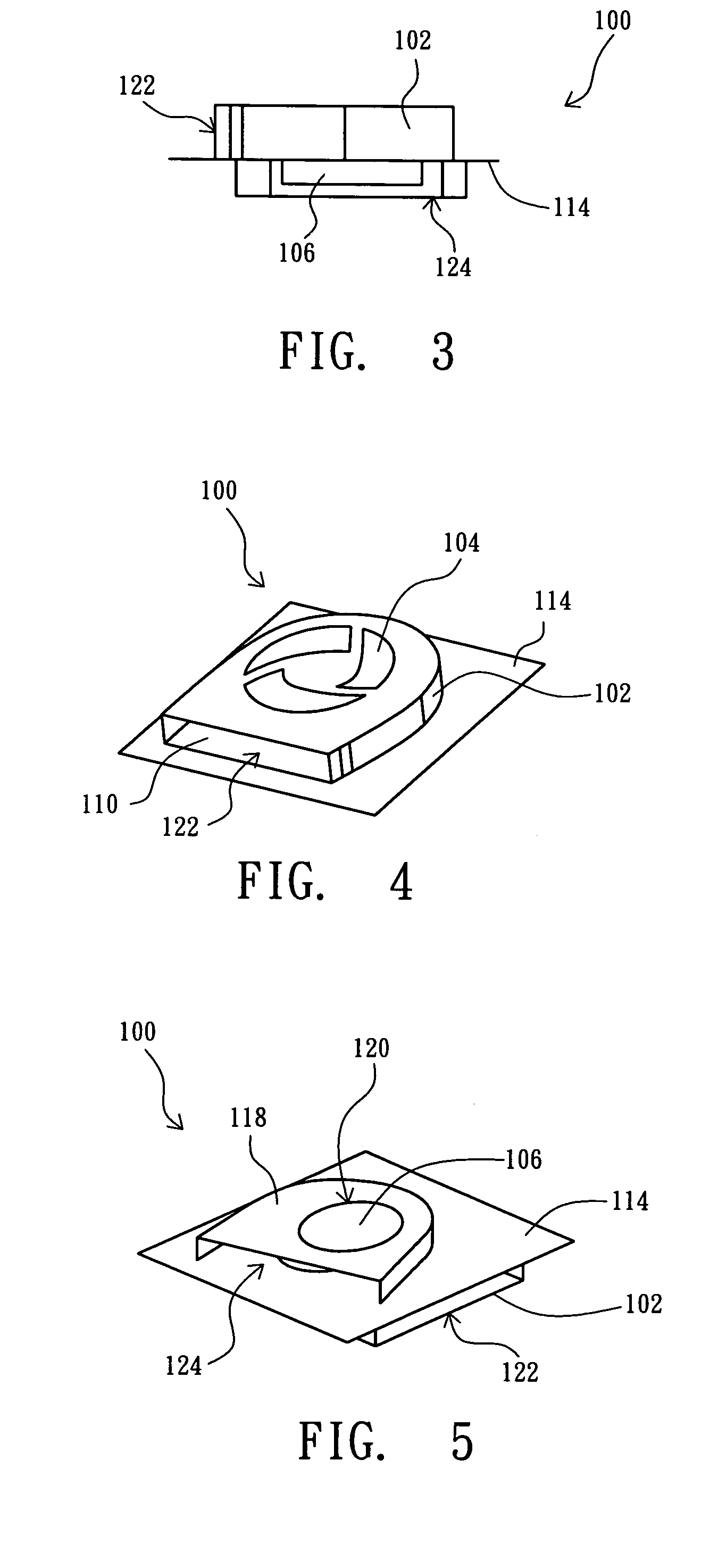
[0021]The present invention discloses a multi-layer and multi-direction fan device. The multi-layer and multi-direction fan device includes a tower radial fan such that the multi-layer and multi-direction fan device can provide sufficient heat dissipation to lower the temperature of the whole system and thereby prolong the life of the system. In order to illustrates the present invention clearly, the following description is stated with reference to FIGS. 1–8b.

[0022]Referring to FIG. 1 and FIG. 2, FIG. 1 illustrates a schematic diagram showing the assembling of a multi-layer and multi-direction fan device in accordance with a preferred embodiment of the present invention, and FIG. 2 illustrates a schematic diagram showing the assembling of a lower cover of a multi-layer and multi-direction fan device in accordance with FIG. 1. The multi-layer and multi-direction fan device 100 can be installed in a printed circuit board 114 of a computer system, for example. The multi-layer and mul...


PUM

PropertyMeasurementUnit
diameteraaaaaaaaaa
electrical energyaaaaaaaaaa
temperatureaaaaaaaaaa

Abstract

A multi-layer and multi-direction radial fan device is disclosed, comprising an upper cover, a tower fan body, a cavity partition and a lower cover. The tower fan body is located in the upper cover, and the tower fan body comprises a first fan layer and a second fan layer. The cavity partition is located under the upper cover, wherein the cavity partition comprises an opening, and the tower fan body extends through the opening so as to make the first fan layer between the upper cover and the cavity partition. The lower cover is located under the cavity partition, wherein the lower cover comprises an opening to expose the bottom surface of the second fan layer, and the second fan layer is located between the cavity partition and the lower cover.

Description

FIELD OF THE INVENTION[0001]The present invention relates to a multi-layer and multi-direction radial fan device, and more particularly, to a multi-layer and multi-direction radial tower fan device.BACKGROUND OF THE INVENTION[0002]With the rapid development of information technology and highly popularized applications of computers, portable and miniature electronic instruments have been extensively used in daily life. In pursuit of facility and practicality, the tendency of current portable electronic products is toward light, thin, small-footprint designs to meet market expectations. For example, a notebook computer is portable and highly capable of processing large quantities of digital data; thus, the notebook computer is popular and used widely.[0003]With the great advancement of integrated circuit processes and the increasingly rising demand for higher integrated circuit capacities, the designs of current integrated circuits are very delicate and complex. Both users and softwar...

Claims


Application Information

Patent Timeline
Patent Type & Authority Patents(United States)
IPC IPC(8): H05K7/20A47F3/04F01D25/24F01D25/26F04D29/40F24H3/02F28F7/00H01B7/42H01L23/34H02G3/03H05K5/00
CPCH05K7/20172
Inventor TSAI, MONG-HAU
Owner QUANTA COMPUTER INC
Learn More