Floating body cell memory and reading and writing circuit thereof
a floating body cell and memory technology, applied in the field of semiconductor integrated circuit devices, can solve the problems of increasing current consumption, difficult to fabricate a dram cell composed of a conventional type, and inability to accurately discriminate data “1” and “0”
- Summary
- Abstract
- Description
- Claims
- Application Information
AI Technical Summary
Benefits of technology
Problems solved by technology
Method used
Image
Examples
first embodiment
(First Embodiment)
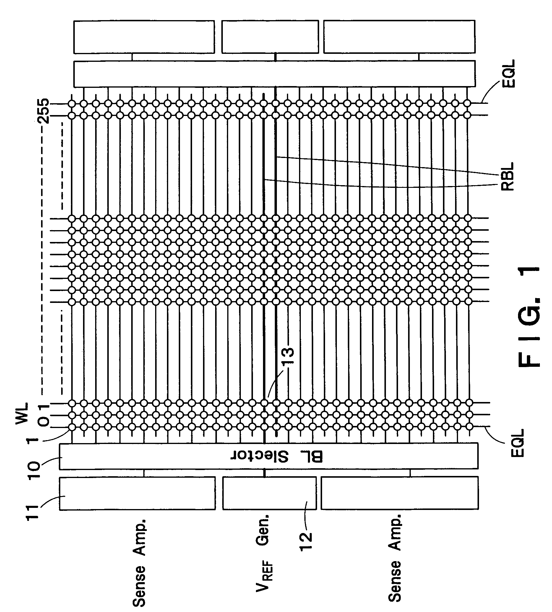
[0063]FIG. 1 is a block diagram showing a schematic configuration of a semiconductor integrated circuit device according to a first embodiment of the present invention. FIG. 1 is a diagram obtained by picking out 256 word lines WL and 32 bit lines BL. Although the whole of one array is shown in the direction of the word line WL, only a part of the one array is shown in the direction of the bit line BL. In practice, a collection that is 32 times as large as the 32 bit lines BL, i.e., a collection having a total of 1,024 bit lines BL forms one array. And a memory is composed of a plurality of arrays.
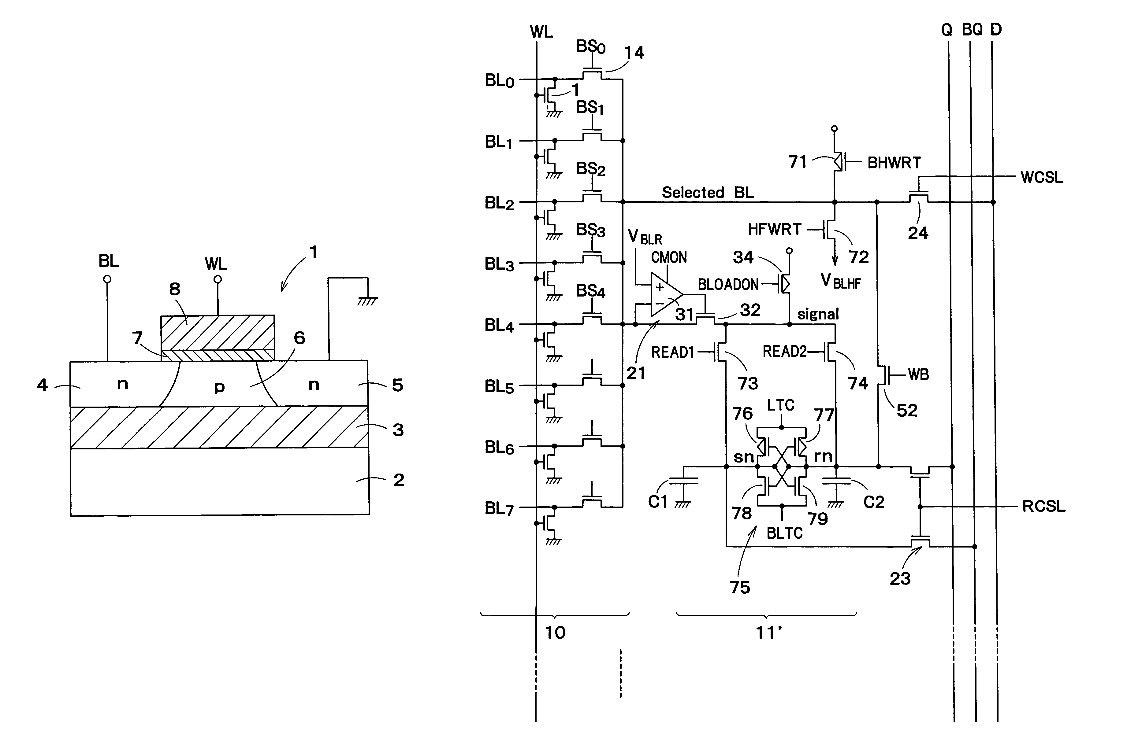
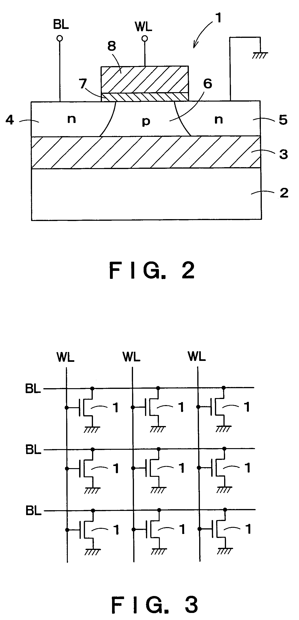
[0064]A DRAM cell 1 formed of an FBC is connected to each of intersections of the word lines WL and the bit lines BL. The DRAM cell 1 is formed of one MISFET having a floating channel body. FIG. 2 is a sectional view showing a structure of a DRAM cell 1 using an n-channel MISFET. An insulation film 3 such as a silicon oxide film is formed on a silicon substrate 2. On the ...
second embodiment
(Second Embodiment)
[0103]In a second embodiment, a dynamic sense amplifier 11 of voltage sense type is provided.
[0104]FIG. 11 is a circuit diagram according to a second embodiment of the sense amplifier block 11. In FIG. 11, components common to FIG. 8 are denoted by like characters, and hereafter different points will be mainly described.
[0105]The sense amplifier shown in FIG. 11 is a dynamic sense amplifier of voltage sense type. The sense amplifier includes a latch circuit 51 for latching a potential difference between an output node bsn of a level limiter 21 and an output node sn of a reference potential generator circuit 12, a p-FET 25 for conducting switching control to determine whether to set the reference bit line RBL to the “1” potential, a p-FET 26 for conducting switching control to determine whether to set the reference bit line RBL to the “1 / 2 ” potential, a write back control transistor 52, a read control circuit 23, and a write control circuit 24.
[0106]The latch circ...
third embodiment
(Third Embodiment)
[0114]A third embodiment is a variant of the second embodiment.
[0115]FIG. 13 is a circuit diagram of a third embodiment of the sense amplifier block 11. In FIG. 13, components common to FIG. 11 are denoted by like characters, and hereafter different points will be mainly described.
[0116]The sense amplifier shown in FIG. 13 is the same as the circuit described in detail in T. N. Blalock and R. C. Jaeger, “A High-Speed Clamped Bit-Line Current-Mode Sense Amplifier,” IEEE J. Solid State Circuits, vol. 26, No. 4, pp. 542–548, April 1991.
[0117]The sense amplifier shown in FIG. 13 is different in the configuration of the latch circuit 51 from the sense amplifier shown in FIG. 11. The latch circuit 51 shown in FIG. 13 includes a p-FET 63 and n-FETs 64 to 67 besides the p-FETs 53 and 54 and the n-FETs 55 and 56. The p-FET 53, n-FET 55 and n-FET 65 are connected in cascade. The p-FET 54, n-FET 56 and n-FET 66 are connected in cascade.
[0118]The output of the level limiter 21...
PUM
 Abstract
Description
Claims
Application Information
 - R&D
- Intellectual Property
- Life Sciences
- Materials
- Tech Scout
- Unparalleled Data Quality
- Higher Quality Content
- 60% Fewer Hallucinations
Browse by: Latest US Patents, China's latest patents, Technical Efficacy Thesaurus, Application Domain, Technology Topic, Popular Technical Reports.
© 2025 PatSnap. All rights reserved.Legal|Privacy policy|Modern Slavery Act Transparency Statement|Sitemap|About US| Contact US: help@patsnap.com


