The problem in this kind of springs is that they are too long.
However, at the dimensions needed to probe ICs with pad pitches below 150 μm the freestanding springs have insufficient strength to hold backside photo
resist without significantly reducing the probe height required for compliance.
Any non-uniformity in the photo process also translates to non-uniform spring heights that cannot meet the uniformity requirements necessary to stay on the IC pads while testing.
The method described in application (WO 01 / 48870)) also has an additional problem in controlling lift height after plating.
Both of these
stress conditions are difficult to control for the tolerances and spring lift uniformity needed to test ICs.
In addition, compressive springs are stronger than tensile springs and the spring with a compressive plated film loses lift height to the point that there is not enough compliance for it to still be a useful probe.
There is also a limit to how high a freestanding spring can be lifted prior to plating to compensate for this compression effect.
As a result, the process taught by this
patent application does not meet the requirements for controlling uniformity of the lift height of arrays of springs required for
IC testing.
As a result, the freestanding portion of the spring is mechanically weaker in the vicinity of the base region.
Because the
bending moment is the highest in this region, upon application of a force to the spring tip during IC test, the springs fracture early and therefore can not meet the probe lifetime requirement needed in
IC manufacturing lines.
The
mask alignment and control of spring release process also
pose serious problems resulting in uneven plating and a variation in lift uniformity.
Another major problem in this process arises from the
high resistivity of the relatively thin release layer, as well as the stress
metal film, through which the plating current flows.
As a result, this process does not produce arrays of springs with reasonably uniform and controlled properties, such as lift height that is essential for effective
IC testing.
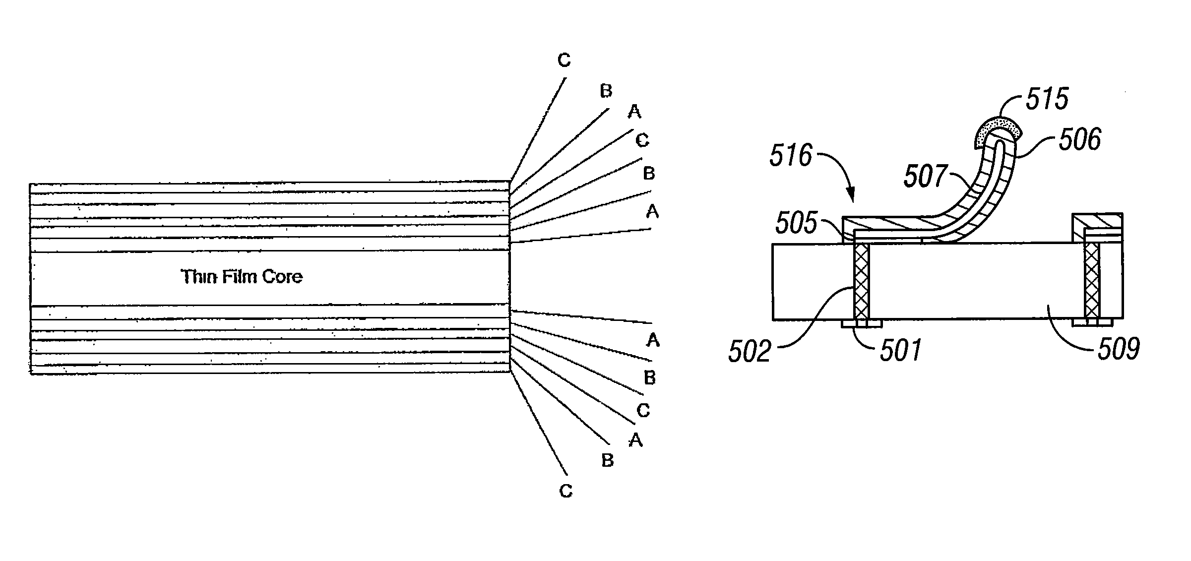
The miniaturized contact springs are subjected to a large number of contact operations during testing which subject the springs to various levels of stresses including cyclic stresses.
Also, in packages that use contact springs to join two components, such as chips and
chip carriers, the springs are subjected to stresses during testing and operation.
However, we have observed that the miniaturized springs, such as those with a size of around 400 μm×60 μm×20 μm, start to fail, i.e. being plastically deformed and / or fractured, typically after 10,000 touchdowns, where the
contact force exceeds about 1 gf.
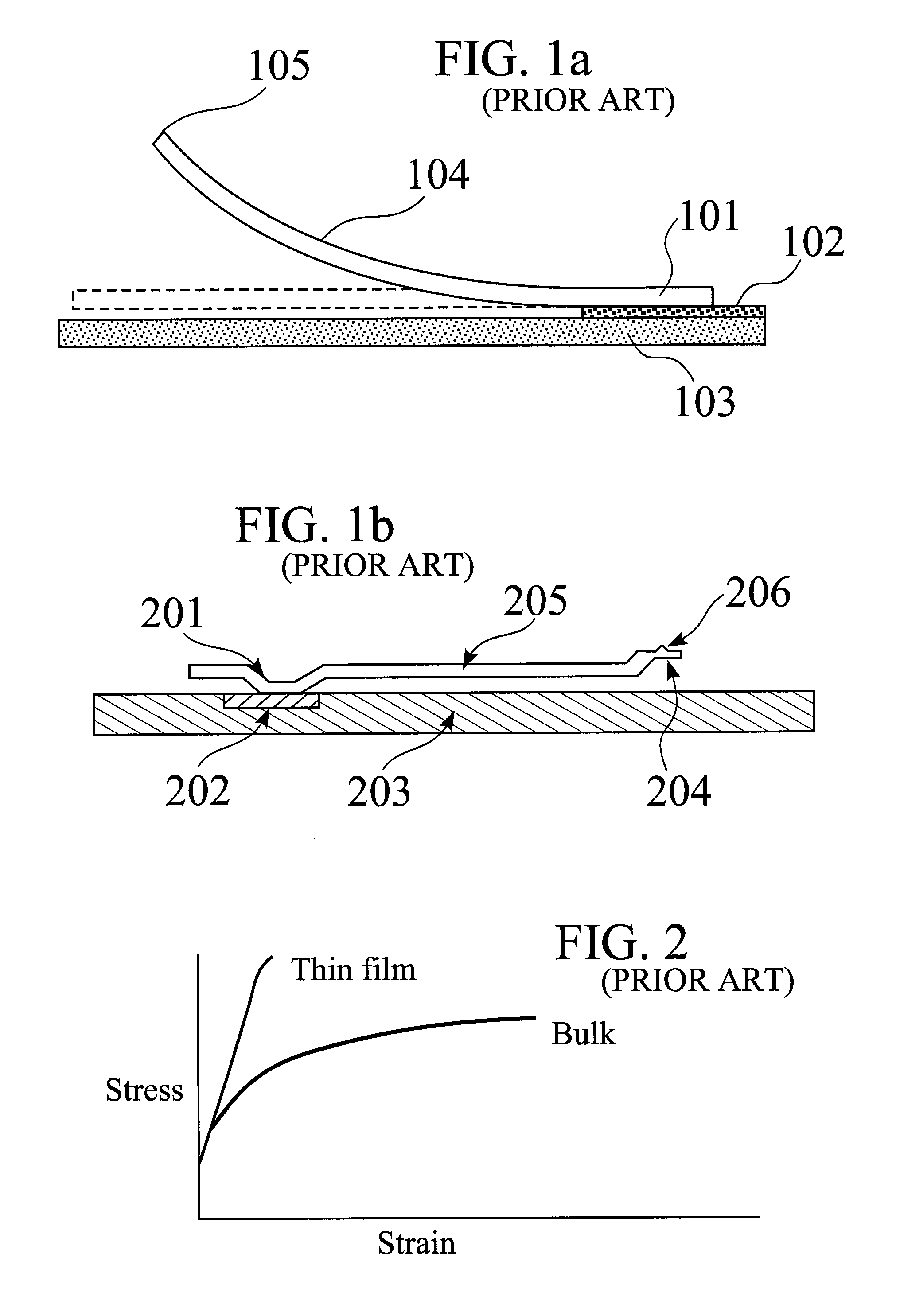
A major reason of the failure is that the resulting alternating stresses exceed fatigue strength of the spring material.
Springs with larger cross-sections can withstand similar or larger force without failure because the resulting stresses are lower, but they limit the
pitch at which springs can be built.
However, a higher
contact force increases the stress developed in the body of the spring, particularly near the base region, and thus increases the probability of early spring failure during repeated touchdowns.
This also shortens the springs' lifetime.

