
Full-color display device

Active Publication Date: 2006-10-24
DENSO CORP
View PDF13 Cites 23 Cited by
  • Summary
  • Abstract
  • Description
  • Claims
  • Application Information

AI Technical Summary

Benefits of technology

[0007]The display control means controls the light source unit to emit light at high intensity when displaying a warning sign or other items on the screen in a single color similar to one of the RGB. By emitting light for displaying warning sign or other items at high intensity, the visibility of the sign or the items improves.

Problems solved by technology

However, the visibility of the warning sings is not good if they are lit in one of or close to the three primary colors, such as red or orange.

Method used


Image

  • Full-color display device
  • Full-color display device
  • Full-color display device

Examples


first embodiment

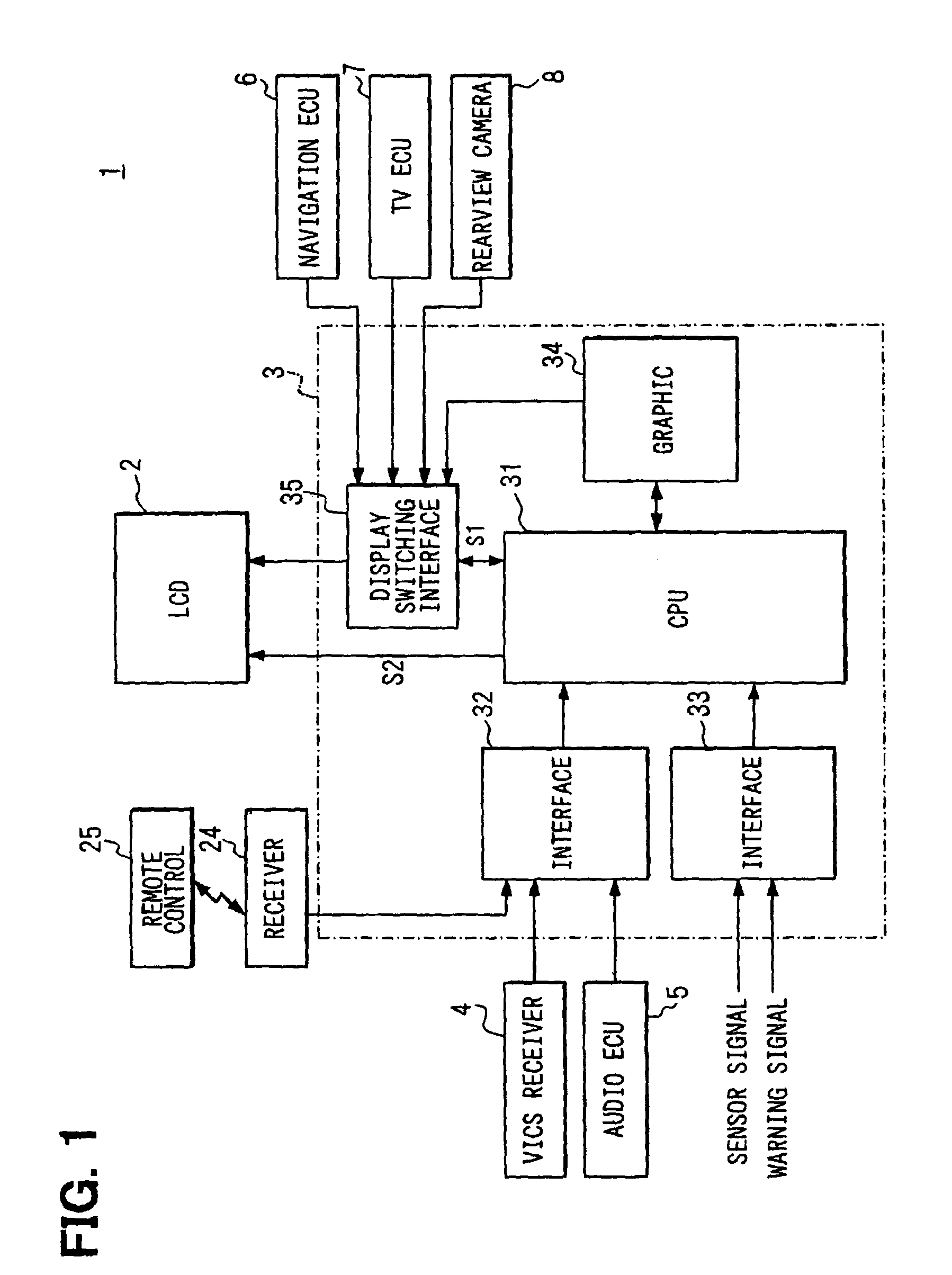
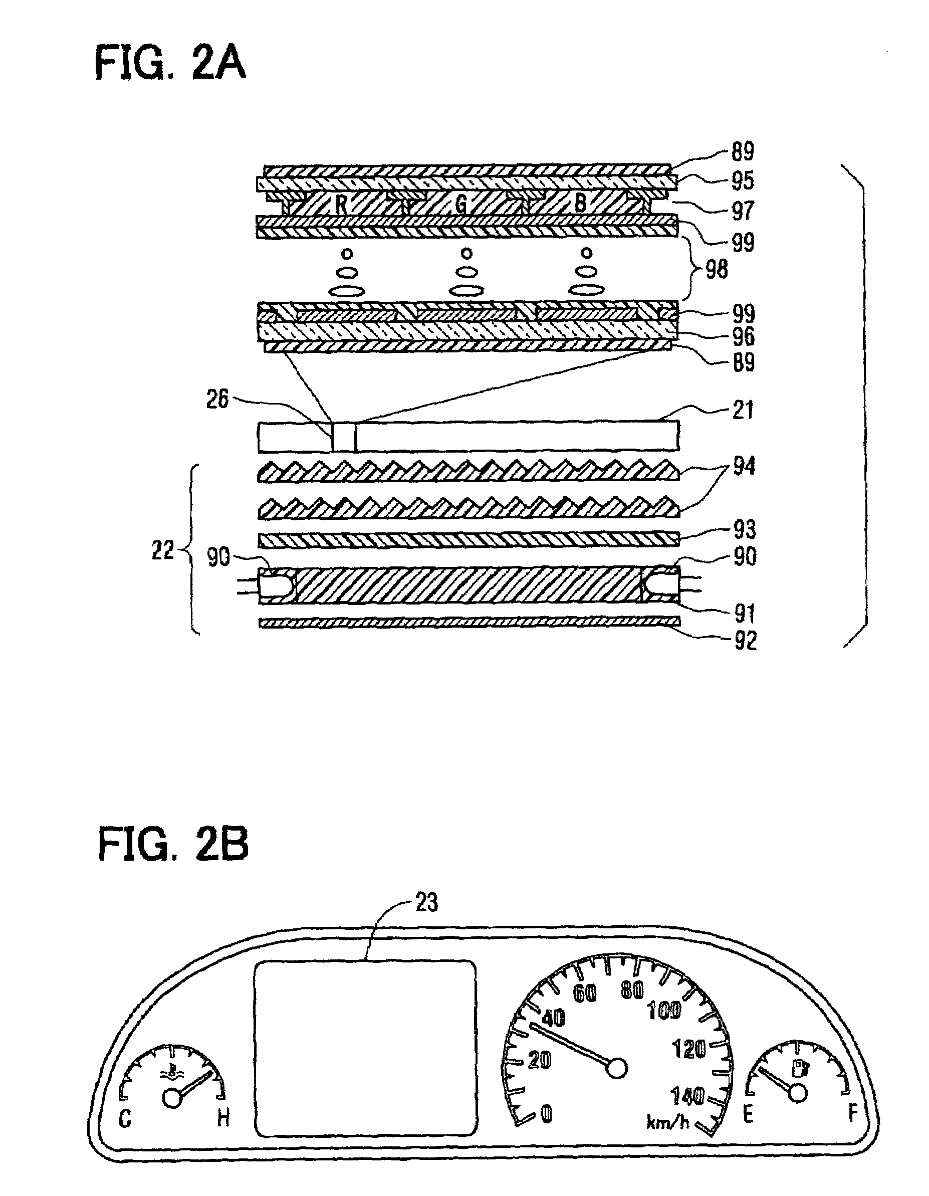
[0023]Referring to FIG. 1, a display device includes a sidelight-type thin film transistor (TFT) liquid crystal display (LCD) 2 and an LCD electronic control unit (ECU) 3 that controls the LCD 2. The display device is included in a monitor system 1 that provides various kinds of information to a user in a vehicle. The user can selects information to be displayed on the LCD via a remote control device 25. A remote control signal is transmitted from the remote control device 25 to the LCD ECU 3 via a receiver 24.

[0024]The monitor system 1 includes the LCD 2, the LCD ECU 3, a vehicle information and communication system (VICS) receiver 4, an audio ECU 5, a navigation ECU 6, a television (TV) ECU 7, and a rear monitor camera 8. The LCD 2 is mounted in an instrument panel of a vehicle at a position visible from a driver. The ECU 3 is a display control means and connected to the LCD 2 in the instrument panel. The VICS receiver 4, the audio ECU 5, the navigation ECU 6, the TV ECU 7, and th...

second embodiment

[0038]Referring to FIG. 6, the LCD 2 includes only white LEDs 90a as light sources. The white LEDs 90a have capabilities of producing light that provides enough brightness for normal full-color display at 80% of the maximum intensity Imax. Therefore, the white LEDs 90 are turned on at 80% of the maximum intensity Imax for the normal full-color display and at 100% of the maximum intensity Imax for warning sign display.

[0039]The above-described control is performed by the LCD ECU 3 as shown in FIG. 7. A LCD display control is performed for selecting the information to be displayed on the screen 23 (S200). In the display control, the information to be displayed on the screen 23 is determined and image data required for displaying the information is produced. Then, a fading rate F, which is a rate at which the intensity of each white LED 90a is reduced from a predetermined intensity, is determined (S210).

[0040]More specifically, the LCD ECU 3 receives an intensity signal indicative of a...

third embodiment

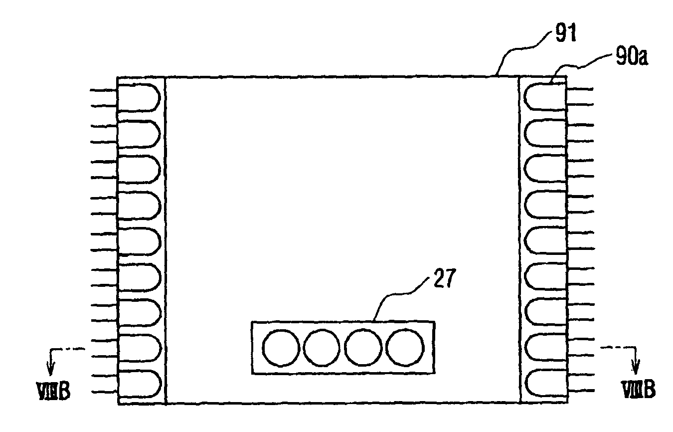
[0045]Referring to FIG. 8A, a warning display area 27 is provided in a part of the display screen 23. White LEDs 90a are arranged at both side edge of the light guide plate 91. Red LEDs 90b are arranged behind the warning display area 27, which is a predetermined display area, of the light guide plate 91. Light shielding plates 91a are mounted around the red LEDs 90b for reducing a leak of light.

[0046]The CPU 31 performs the LCD control process in the same manner as the first embodiment shown in FIG. 5. However, warning information is selected for display in the warning display area 27 and information other than the warning information is selected for display in the rest of the screen 23 in step S100. In other words, the warning information and the other information are displayed on the screen 23 simultaneously.


PUM


Abstract

A full-color liquid crystal display device (TFT-LCD) installed in a monitor system for a vehicle includes a liquid crystal display (LCD), an LCD electronic control unit (ECU). The LCD has a backlight unit that includes white LEDs and red LEDs. The LCD ECU performs a display control process for selectively displaying navigation information, a tachometer image, or other information. A warning sign is displayed in a single color red in a display area of the LCD if required. The LCD ECU selects information to display and determines whether the information is a warning. If the information is a warning, the white LEDs and the red LEDs are turned on for displaying a warning sign indicative of the warning at high intensity so that the sign is easily recognized. If the information is not a warning, only the white LEDs are turned on.

Description

CROSS REFERENCE TO RELATED APPLICATION[0001]This application is based on and incorporates herein by reference Japanese Patent Application No. 2002-232517 filed on Aug. 9, 2002.FIELD OF THE INVENTION[0002]The present invention relates to a full-color display device for displaying full-color images by controlling intensity of three primary colors of light, which are red, green, and blue (RGB), in each pixel.BACKGROUND OF THE INVENTION[0003]For full-color display devices, a liquid crystal display (LCD), a plasma display panel (PDP), and an electroluminescent display (ELD) are commonly known. The LCD is a reactive-type (non-luminescent-type) display and has a display region consists of many pixels. Each pixel is divided into a red (R) region, a green (G) region, and a blue (B) region. The R, G, and B regions have a red filter, a green filter, and a blue filter, respectively. RGB components in a white light emitted from the backlight unit are selectively passed to a front surface of the ...

Claims


Application Information

Patent Timeline
IPC IPC(8): G09G3/36G02F1/1335B60K35/00G02F1/133G02F1/13357G09G3/34H01J1/62
CPCB60K35/00G02F1/133603G09G3/3413B60K37/02B60K2350/1072B60K2350/2021B60K2350/2034B60K2350/355G09G3/3611G09G2320/062G09G2320/0626G09G2320/0633G09G2360/144B60K35/60B60K35/213B60K2360/25B60K2360/331B60K35/80B60K2360/55
Inventor NISHIKAWA, RYOICHI
Owner DENSO CORP
Learn More