Polarity protection implemented with a MOSFET

a mosfet and polarity protection technology, applied in the direction of automatic disconnection emergency protection arrangements, electrical equipment, circuit arrangements of boards/switchyards, etc., can solve the problems of complex control circuit, large power loss of diodes, annoying disturbances in operation, etc., and achieve low power loss and simple control circuit

Inactive Publication Date: 2006-10-24
CORIANT
View PDF10 Cites 12 Cited by
  • Summary
  • Abstract
  • Description
  • Claims
  • Application Information

AI Technical Summary

Benefits of technology

[0014]The power loss is low in the solution according to the invention. In addition the control circuit is simple. The MOSFET can be rapidly controlled into the non-conducting state in case the battery voltage is short-circuited. When the MOSFET is in the non-conducting state no current can flow in the wrong direction, and it will not destroy any components.

Problems solved by technology

Polarity protection is required particularly in telecommunications equipment where even a momentary break can cause annoying disturbances in the operation.
However, a diode has a considerable loss of power, particularly at higher currents.
The known polarity protections realised with a MOSFET have problems regarding the complex control circuit, the expensive structure and / or the slow function.

Method used


Image

  • Polarity protection implemented with a MOSFET
  • Polarity protection implemented with a MOSFET
  • Polarity protection implemented with a MOSFET

Examples


Embodiment Construction

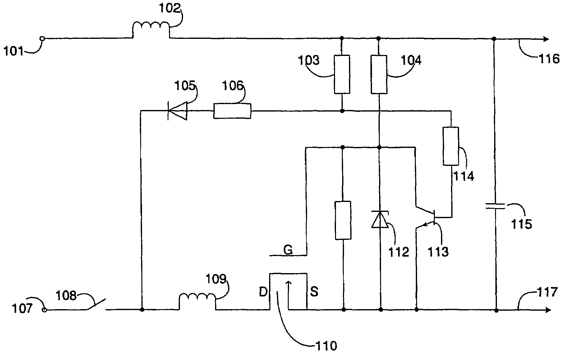
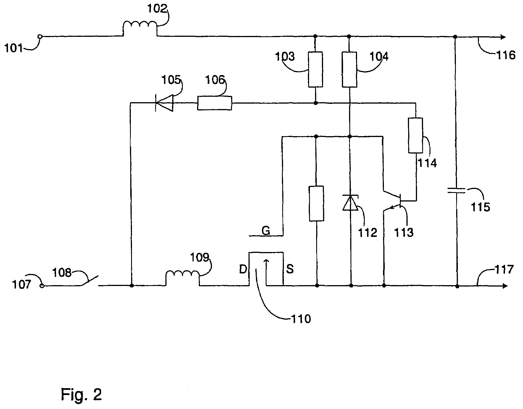
[0018]In the embodiment shown in FIG. 2 a device, i.e. the load, utilising the polarity protection is connected to the output of the illustrated protective circuit, to its positive 116 and negative 117 terminals. The voltage used by the load is supplied from the positive 101 and negative 107 terminals of a power supply, for instance a battery. The current flows from the positive terminal 101 of the power supply to the load 116. The coil 102 acts as a part of the electromagnetic protection (EMC) protection, so that it retards changes occurring in the current. The resistance 103 is selected to be so large that the voltage divider circuit via the resistor 106 to the diode 105 or via the resistor 114 to the base of the transistor 113 consumes almost no current in normal operation. In addition the circuit contains a capacitor 115 in front of the load.

[0019]The current coming from the load 117 flows through the MOSFET 110, the coil 109 and the switch 108 to the negative terminal 107 of th...


PUM


Abstract

A polarity protection circuit contains a metal oxide semiconductor field effect transistor (FET) that pets its control voltage via an electrical connection from supply voltage lines and a transistor that pets its control voltage via another connection from the supply voltage lines. When a supply voltage has a wrong polarity the FET is in a non-conducting state. If in the supply voltage lines during normal operation there occurs a short circuit that tends to chance a direction of the current, the transistor rapidly discharges a gate charge of the FET, and the current flow in the wrong direction is prevented.

Description

TECHNICAL FIELD[0001]The invention relates to the use of a metal oxide semiconductor field effect transistor (MOSFET) as polarity protection, and particularly to a transistor control circuit, which can be implemented in a manner as simple and advantageous as possible.BACKGROUND OF THE INVENTION[0002]Electronic circuits are often protected against wrong polarity. The task of the polarity protection is to enable a current flow only in one particular direction. A current in the opposite direction can be caused e.g. by a battery or cable connected in a wrong way in installation stage. Then the polarity protection prevents short-circuiting of the battery and destruction of components. The polarity protection secures the operation of the equipment, also during a momentary short circuit in the battery's supply line. If there is a momentary short circuit or a lowered voltage in the supply lines between the battery and the load, then the capacitors connected in parallel with the load will ma...

Claims


Application Information

Patent Timeline
Patent Type & Authority Patents(United States)
IPC IPC(8): H02H3/18H02B1/24H02H11/00
CPCH02H11/003
Inventor JOKINEN, SAMI
Owner CORIANT
Why Eureka
Try Eureka