Automatic selection of cranial remodeling device trim lines

a technology of cranial remodeling and automatic selection, which is applied in the field of automatic generation of cranial remodeling device configuration, can solve the problems of inability of scanners to obtain instantaneous capture of data of the entirety of an infant's head, use of expert systems, and inability to optimize the solution of developing modified shapes suitable for producing cranial remodeling devices

Active Publication Date: 2006-10-24
CRANIAL TECH
View PDF7 Cites 78 Cited by
  • Summary
  • Abstract
  • Description
  • Claims
  • Application Information

AI Technical Summary

Benefits of technology

[0019]In accordance with the principles of the invention a digitizer is utilized to capture a three dimensional digital image of a deformed head to produce first digital data. The first digital data is utilized by a computer to automatically provide cranial remodeling device configuration information for use in fabricating a cranial remodeling device for the deformed head. In accordance with the principles of the invention, the configuration information comprises trim line information for a cranial remodeling device. The computer includes one or more computer programs that are trainable to automatically provide the trim line information. In the illustrative embodiment of the invention, the trainable computer programs comprise neural networks.

Problems solved by technology

Such arrangements have the disadvantage in that scanners cannot obtain instantaneous capture of data of the entirety of an infant's head.
However, because each head shape is unique, even the use of an expert system may not present an optimized solution to developing modified shapes suitable for producing a cranial remodeling device.
The difficulty with systems of this type is that to scan a three-dimensional object, the scan times limit use of the systems to stationary objects.
Capturing of such an image has not been possible with prior image capturing systems for a variety of reasons, one of which being that infants are not stationary for the times that prior systems require to scan or capture the data necessary to produce a three-dimensional image.
Prior digitization techniques and systems fail to recognize the particular unique challenges and requirements necessary for a system for the production of digital images of infant heads.
The younger infants are not able to follow verbal instructions and are not able to demonstrate head control while the older infants are difficult to control for more than a brief moment of time.
Laser scanning methods have the disadvantage of the long time, typically 14–20 seconds, that is required to scan an object.
However even this scan rate is too slow for an unrestrained infant.
Structured-light Moire and phase-shifted Moire systems used in certain 3D imaging systems are difficult to calibrate, are costly, and are relatively slow and therefore are not suitable for use in obtaining images of infants.
In addition these systems are incapable of capturing the entirety of an object in one time instant.
Computed Tomography (CT) and Magnetic Resonance Imaging (MRI) are not particularly useful for the present application simply due to size, expense and concerns regarding radiation and the need to anesthetize the infant.
Prior systems that rely solely on triangulation of digital cameras proved to have insufficient accuracies, particularly as the object being imaged varied in shape and size from a calibration standard.
Structured light systems that combined triangulated digital cameras with a projected grid or line pattern can capture only one surface at a time because the grids projected by multiple projectors interfered with each other resulting in a loss of data.

Method used


Image

  • Automatic selection of cranial remodeling device trim lines
  • Automatic selection of cranial remodeling device trim lines
  • Automatic selection of cranial remodeling device trim lines

Examples


Embodiment Construction

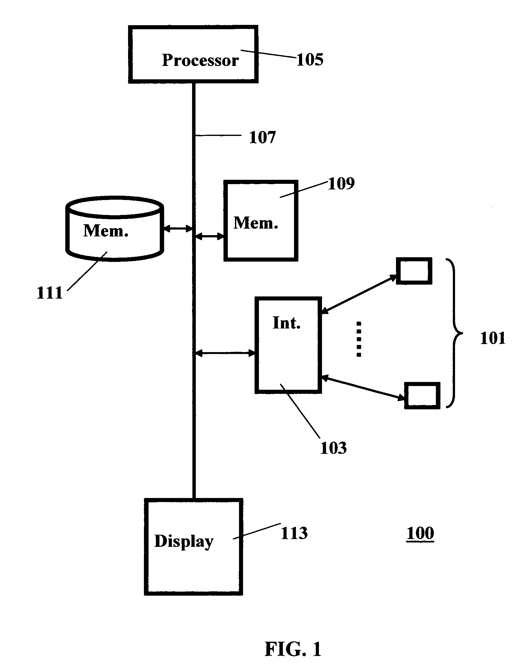
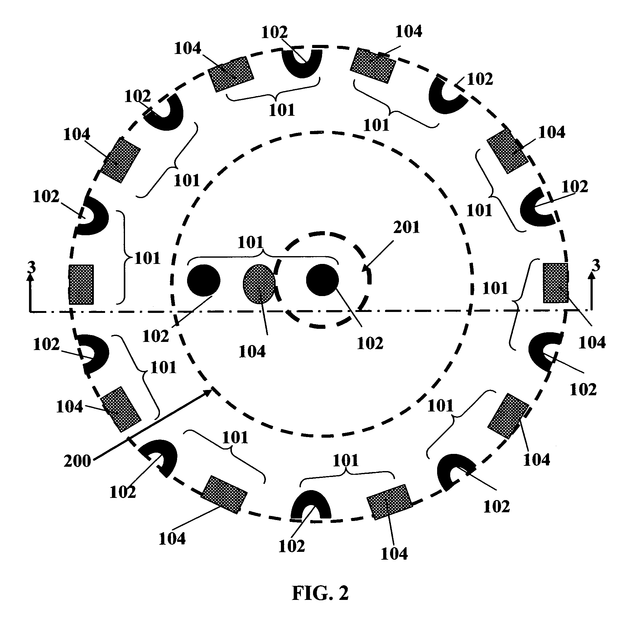
[0047]Turning now to FIG. 1, a block diagram of an image capture system or digitizer 100 is shown in block diagram form. System 100 includes a plurality of image capturing apparatus 101. Each image capturing apparatus is operable such that a three-dimensional image is captured for a surface portion of an object that is disposed within the field of view of the image capturing apparatus.

[0048]The image capturing apparatus 101 are all coupled to and controlled by processing apparatus 105 via a bus 107. In addition processing apparatus 105 has associated with it program memory 109 and data memory 111. It will be understood by those skilled in the art that processing apparatus 105 may include one or more processors that are commercially available from a wide variety of sources, such as the Intel Pentium 4 or Itanium chip based processors. Program memory 109 and data memory 111 may be the same memory, or each may comprise a plurality of memory units.

[0049]Program memory 109 includes an im...


PUM


Abstract

A method and system for producing cranial remodeling devices to correct for head deformities in infants is described. The system operates on three dimensional digital captured data of a head to automatically provide trim line information for each cranial remodeling device.

Description

RELATED APPLICATIONS[0001]This application is a continuation-in-part of copending U.S. application Ser. No. 10 / 385,307 filed Mar. 10, 2003, for Three-Dimensional Image Capture System by T. Littlefield and J. Pomatto and assigned to a common assignee. The following related patent applications are being filed on even date herewith and are assigned to a common assignee: Ser. No. 10 / 753,012 Method And Apparatus For Producing Three Dimensional Shapes by T. Littlefield, J. Pomatto and G. Kechter: Ser. No. 10 / 753,013 Cranial Remodeling Device Database by T. Littlefield and J. Pomatto: Ser. No. 10 / 753,118 Automatic Selection of Cranial Remodeling Device Configuration T. Littlefield and J. Pomatto: and Ser. No. 10 / 752,800 Cranial Remodeling Device Manufacturing System by T. Littlefleld and J. Pomatto. The disclosures of the above-identified applications are incorporated herein.FIELD OF THE INVENTION[0002]This invention pertains to a method and apparatus for automatically providing a cranial ...

Claims


Application Information

Patent Timeline
Patent Type & Authority Patents(United States)
IPC IPC(8): G06K9/00A61F5/00G06E1/00G06E3/00G06F15/18G06G7/00G06G7/48G06G7/58G06T1/00G06T7/00G06T17/10
CPCA61F5/05891G06T1/0007G06T7/0051G06T17/10G06T2207/30004G06T2210/41G06T7/50B33Y50/00B33Y80/00
Inventor LITTLEFIELD, TIMOTHY RPOMATTO, JEANNE K
Owner CRANIAL TECH
Why Eureka
Try Eureka