Dual temperature closed loop cooling system

Active Publication Date: 2006-10-31
BRP US +1
View PDF17 Cites 33 Cited by
  • Summary
  • Abstract
  • Description
  • Claims
  • Application Information

AI Technical Summary

Benefits of technology

[0010]It would therefore be desirable to provide a closed loop coolin

Problems solved by technology

In general, during fuel combustion in an internal combustion engine, a considerable amount of heat is generated.
While the engine is designed to operate at relatively high temperatures, operating at excessive temperatures for extended periods of time is detrimental to engine efficiency and, if unaddressed, can shorten the operating life of an engine.
Additionally, operating at temperatures below a desired operating temperature can have just as adverse consequences.
For example, operating at too low a temperature can increase soot and condensation buildup in the engine, increase emissions, and reduce fuel efficiency.
While this construction serves many needs satisfactorily and allows for a relatively simple construction of the cooling system, such cooling systems do have drawbacks.
One drawback to the open loop cooling system is that the quality of the coolant circulated through the internal passageways of the engine is variable.
Such obstruction hinders cooling of the engine in the vicinity of the blockage and can result in localized “hot-spots” during engine operation.
These hot-spots are detrimental to engine performance and can result in premature engine failure if left unaddressed.
Decreasing the screen openings to further limit the ingress of contaminates only promotes screen blockage and hinders adequate coolant passage.

Method used


Image

  • Dual temperature closed loop cooling system
  • Dual temperature closed loop cooling system
  • Dual temperature closed loop cooling system

Examples


Embodiment Construction

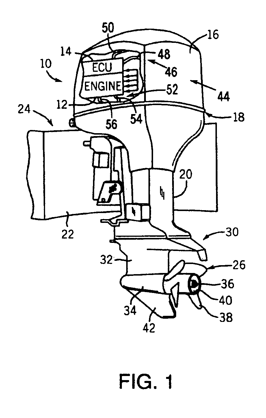
[0023]The present invention relates generally to internal combustion engines, and preferably, those incorporating auxiliary equipment that may benefit from cooling at a temperature different than that of the engine. FIG. 1 shows an outboard motor 10 having an engine 12 controlled by an electronic control unit (ECU) 14 under engine cover 16. Engine 12 is housed generally in a powerhead 18 and is supported on a mid-section 20 configured for mounting on a transom 22 of a boat 24 in a known conventional manner. Engine 12 has a vertical crankshaft (not shown) and is coupled to transmit power to a propeller 26 to develop thrust and propel boat 24 in a desired direction. A lower unit 30 includes a gear case 32 having a bullet or torpedo section 34 formed therein and housing a propeller shaft 36 that extends rearwardly therefrom. Propeller 26 is driven by propeller shaft 36 and includes a number of fins 38 extending outwardly from a central hub 40 through which exhaust gas from engine 12 is...


PUM


Abstract

A cooling system and method of cooling an engine are disclosed. The cooling system includes a first closed loop that circulates coolant at a first temperature and a second closed loop that circulates coolant at a second temperature that is different than the first temperature. Such a construction provides two separate cooling temperature circuits for cooling equipment at different cooling temperatures.

Description

[0001]The present application claims priority to U.S. Provisional Application Ser. No. 60 / 514,208 dated Oct. 24, 2003, the entirety of which is hereby incorporated into the present application by reference.BACKGROUND OF THE INVENTION[0002]The present invention relates generally to engine cooling systems and, more particularly, to a closed loop cooling system having multiple cooling loops, each having a different operating temperature.[0003]In general, during fuel combustion in an internal combustion engine, a considerable amount of heat is generated. While the engine is designed to operate at relatively high temperatures, operating at excessive temperatures for extended periods of time is detrimental to engine efficiency and, if unaddressed, can shorten the operating life of an engine. Additionally, operating at temperatures below a desired operating temperature can have just as adverse consequences. For example, operating at too low a temperature can increase soot and condensation ...

Claims


Application Information

Patent Timeline
IPC IPC(8): F01P9/00
CPCF01P3/202F01P7/165F01P2005/105F01P2025/50F01P2050/30F01P2060/10
Inventor WESTHOFF, JR., PAUL E.DOPONA, MICHAEL
Owner BRP US
Why Eureka
Try Eureka