
Method for forming shallow trench isolation structure with anti-reflective liner

a technology of anti-reflective liner and shallow trench, which is applied in the direction of semiconductor/solid-state device manufacturing, basic electric elements, electric devices, etc., can solve the problems of localized stress-related defects, dislocation and cracking, and concentrated thermal-mechanical stress buildup at the bottom corners, so as to reduce the “kink effect” and reduce the stress buildup. , the effect of less stress buildup

Inactive Publication Date: 2006-10-31
INTEGRATED DEVICE TECH INC
View PDF24 Cites 1 Cited by
  • Summary
  • Abstract
  • Description
  • Claims
  • Application Information

AI Technical Summary

Benefits of technology

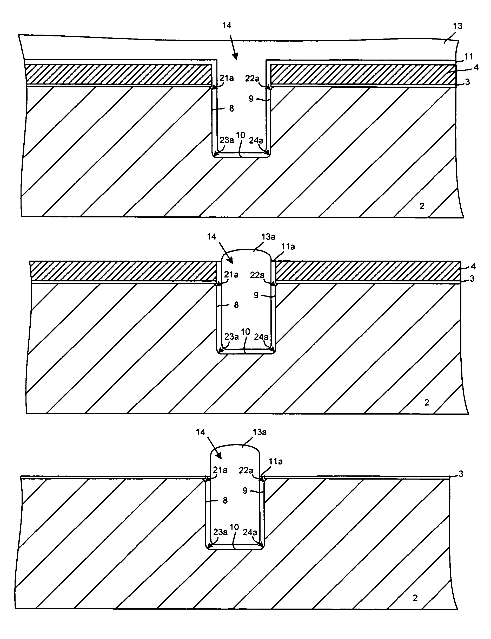
[0010]The heating process for annealing the substrate is performed at a significantly lower temperature than conventional processes for forming oxide trench liners. Accordingly, less stress buildup results as compared to processes that use conventional oxide trench liners. In addition, the trench of the present invention has rounded corners, resulting in reduced stress build up and reduced “kink effect” as compared to prior art trenches having sharp corners. Moreover, the use of an antireflective liner eliminates notching and lifting problems that can result from reflection of light off of the sides of trenches. Accordingly, manufacturing yield is improved, resulting in reduced manufacturing cost.

Problems solved by technology

The sharply angled bottom corners of conventional shallow trench isolation structures result in thermal-mechanical stress buildup concentrated at the bottom corners.
This corner stress buildup can result in localized stress-related defects.
In severe cases, stresses from subsequent process steps and from thermal cycling can cause dislocation and cracking.
This can cause device failure, resulting in reduced manufacturing yield and increased manufacturing costs.
Another problem that can arise with respect to conventional shallow trench isolation structures is electrical field buildup enhancement at top corners of the active area.
This phenomenon, commonly referred as “kink effect,” can produce early turn-on of transistors and undesired cross-talk between adjacent devices.
However, conventional processes for forming oxide trench liners use high temperature processes (often at temperatures of greater than 1,100 degrees centigrade), which stress the substrate, resulting in undesired stress buildup.
However, when the resist thickness is not sufficient to block incoming light, some of the light passes through the resist and into the trenches.
Resist notching exposes areas of the active areas that are supposed to be covered by resist, causing undesired implantation.
Lifting results in resist covering areas that were supposed to be exposed, preventing the implantation of desired impurities.
However, this can result in bridging and may not be practical when features less than 0.13 micron must be formed.

Method used


Image

  • Method for forming shallow trench isolation structure with anti-reflective liner
  • Method for forming shallow trench isolation structure with anti-reflective liner
  • Method for forming shallow trench isolation structure with anti-reflective liner

Examples


Embodiment Construction

[0026]Reference will now be made in detail to the preferred embodiments of the invention, examples of which are illustrated in the accompanying drawings. While the invention will be described in conjunction with the preferred embodiments, it will be understood that they are not intended to limit the invention to these embodiments. On the contrary, the invention is intended to cover alternatives, modifications and equivalents, which may be included within the spirit and scope of the invention as defined by the appended claims. Furthermore, in the following detailed description of the present invention, numerous specific details are set forth in order to provide a thorough understanding of the present invention. However, it will be obvious to one of ordinary skill in the art that the present invention may be practiced without these specific details. In other instances, well-known methods, procedures, components, and circuits have not been described in detail so as not to unnecessarily...


PUM


Abstract

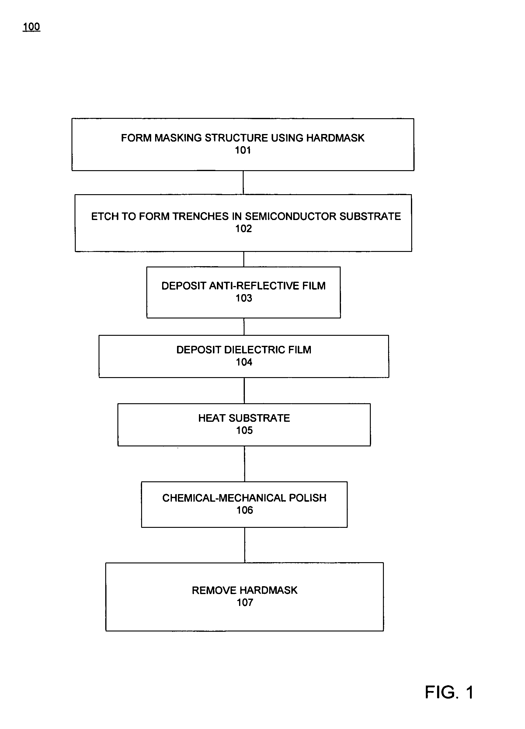
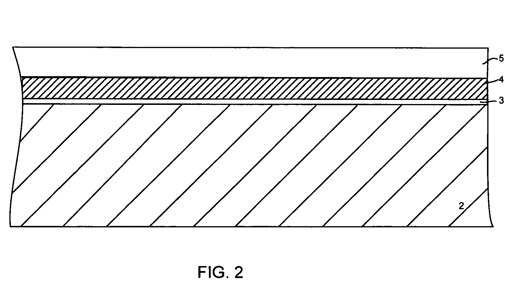
The present invention relates to a shallow trench isolation structure and a method for forming a shallow trench isolation structure on a semiconductor substrate. A masking structure that includes a hard mask is formed over the semiconductor substrate, and an etch is performed so as to form trenches within the semiconductor substrate. An anti-reflective film is deposited such that it extends within the trench. A dielectric film is deposited over the anti-reflective film such that it fills the trench. A heating process step is then performed to anneal the substrate, rounding the corners of the trench. A chemical mechanical polishing process is performed to remove those portions of the anti-reflective film and the dielectric film that overlie the hard mask. The hard mask is then removed, producing a shallow trench isolation structure that prevents lifting and notching in subsequent fabrication steps.

Description

FIELD OF THE INVENTION[0001]The present invention relates to the field of semiconductor devices. More specifically, the present invention relates to semiconductor device shallow trench isolation structures and methods for forming shallow trench isolation structures.BACKGROUND ART[0002]Shallow trench isolation structures are used in semiconductor device fabrication to isolate active areas of the semiconductor substrate. Typically, shallow trench isolation structures are formed by etching the top surface of the semiconductor substrate so as to form trenches that extend into the semiconductor substrate. These trenches surround areas of the semiconductor substrate that are commonly referred to as “active areas.” A layer of oxide is then deposited to fill up the trenches, electrically isolating active areas from each other.[0003]Conventional shallow trench isolation structures usually include trenches that have a flat horizontal bottom and that have vertical sidewalls. The sharply angled...

Claims


Application Information

Patent Timeline
Patent Type & Authority Patents(United States)
IPC IPC(8): H01L21/76H01L21/336
CPCH01L21/76224
Inventor CHEN, CHIH-HSIANGGU, YIMINGLO, GUO-QIANG
Owner INTEGRATED DEVICE TECH INC
Learn More