Method of CD/DVD vibration detection by monitoring motor conditions

a technology of vibration detection and motor conditions, applied in the field of mass storage devices, can solve the problems of increasing the number of broken disks in the high-speed cd/dvd drive, disks have disintegrated, and the cd-rom and dvd drive is being damaged, so as to prevent the destruction of the disk and ensure the safe operation of the cd-rom

Inactive Publication Date: 2006-10-31
GATEWAY
View PDF18 Cites 16 Cited by
  • Summary
  • Abstract
  • Description
  • Claims
  • Application Information

AI Technical Summary

Benefits of technology

[0009]Advantageously, the method and apparatus detects a vibrating condition in a CD-ROM or DVD drive that holds a plastic disk. When vibration is detected a signal is sent to the controller that slows the speed of the spindle. This also prevents loss of data that may be on the disk. This not only prevents destruction of the disk but also prevents destruction of the disk drive or one of its subsystems. The invention also provides for safer operation of a CD-ROM or DVD disk drive.

Problems solved by technology

Spinning the disks at higher spin speeds have resulted in problems associated with CD-ROM and DVD drives.
An increasing number of broken disks are being found in the high speed CD / DVD drives.
Some believe that the disks have disintegrated due to structural defects such as cracks and the like.
Another possibility is that the problem is caused when a disk is spinning at a high rate and begins to vibrate on the disk drive spindle.
When the magnet can no longer hold the vibrating disk, the disk will be released and will spin off of the spindle at a high rate of speed in an uncontrolled direction.
The disk slams against the housing and is destroyed.
The resulting particles may also lodge within critical mechanisms within the drive and result in ruining the disk drive as well.
For example, a plastic portion lodged near a mirror may block the light needed to read from the drive or prevent the mirror movement needed to focus the beam.

Method used


Image

  • Method of CD/DVD vibration detection by monitoring motor conditions
  • Method of CD/DVD vibration detection by monitoring motor conditions
  • Method of CD/DVD vibration detection by monitoring motor conditions

Examples


Embodiment Construction

[0017]In the following detailed description of the preferred embodiments, reference is made to the accompanying drawings which form a part hereof, and in which are shown by way of illustration specific embodiments in which the invention may be practiced. It is to be understood that other embodiments may be utilized and structural changes may be made without departing from the scope of the present invention.

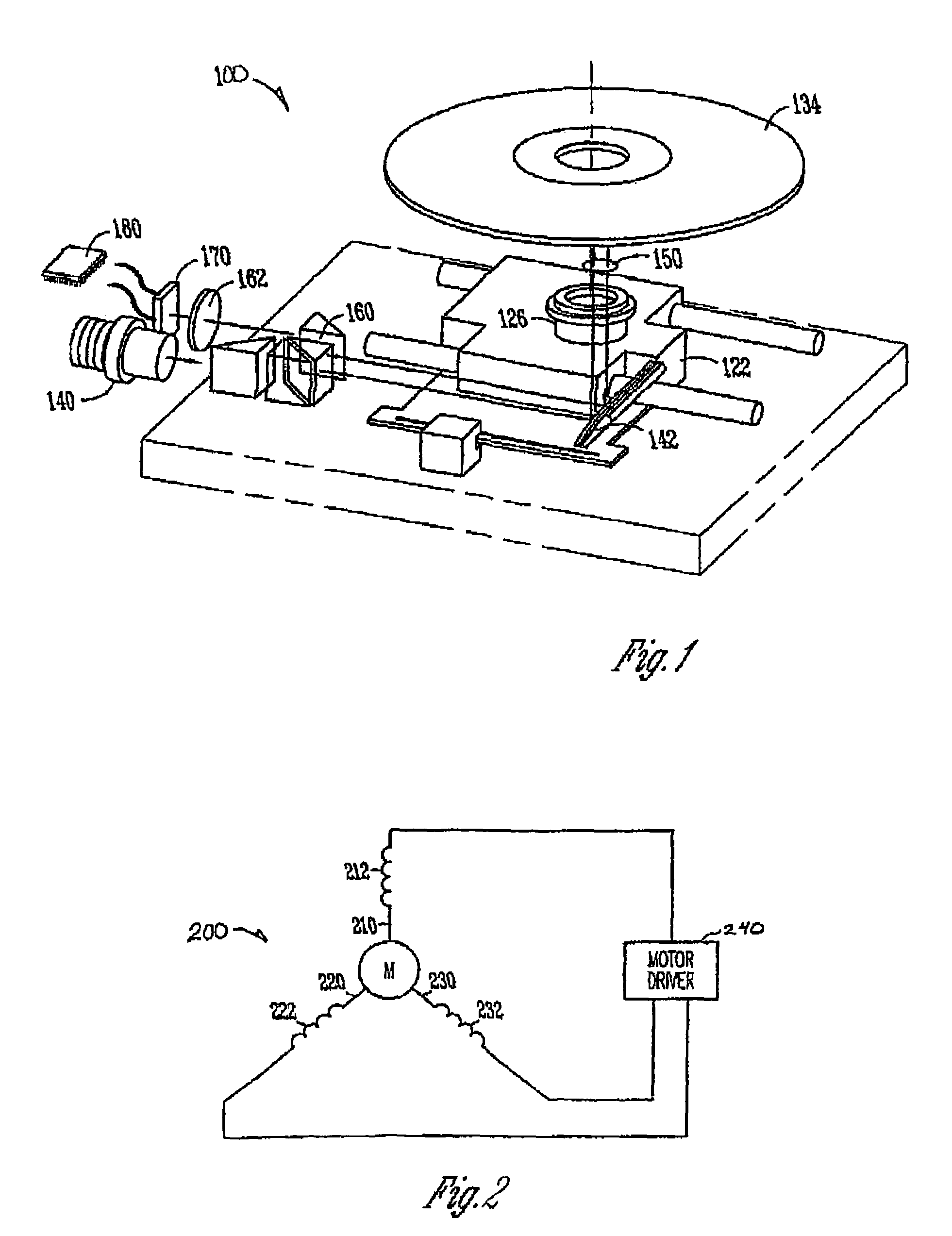
[0018]Referring to FIG. 1, the principal electrical and mechanical components of a disk drive 100 constructed in accordance with a preferred embodiment of the present invention are illustrated. The disk drive includes a base 122 and a cover. Attached to the base 122 is a spindle 126. A disk 134 is placed on the spindle 126. A spindle motor 200 (shown schematically in FIG. 2) rotates the spindle 126 and the disk 134. A spindle motor driver 240 controls either the current, the voltage, or both the current and the voltage within the coils of the spindle motor 200 to produce a torque ...


PUM

PropertyMeasurementUnit
speedaaaaaaaaaa
electrical phase parameteraaaaaaaaaa
electrical parameteraaaaaaaaaa

Abstract

This invention describes a method and apparatus to determine a safe rotational speed for a CD/DVD drive by detecting the amount of vibration of the disk by measuring the operating conditions of the spindle motor. A disk drive includes a motor for rotating the disk and an apparatus for monitoring the current or back emf in the windings of the motor. When the current or the back emf varies from a normal level, the disk is vibrating and a signal indicating a vibration condition is sent to the spindle motor driver. The maximum speed that the disk rotated is slowed until a vibrating condition is no longer detected and the rotational speed associated with a particular disk is based dynamically on the amount of vibration detected. Disks may also be identified that cannot spin a minimum rate of speed.

Description

FIELD OF THE INVENTION[0001]The present invention relates to the field of mass storage devices. More particularly, this invention relates to disk drives that use a plastic medium such as CD, CD-ROM and DVD drives.BACKGROUND OF THE INVENTION[0002]One of the key components of any computer system is a place to store data. Computer systems have many different places where data can be stored. One common place for storing massive amounts of data in a computer system is on a disk drive, such as a CD-ROM or DVD. The most basic parts of a disk drive are a plastic disk that is rotated, an actuator that moves a transducer to various locations over the disk, and electrical circuitry that is used to write and read data to and from the disk. Some of these drives have read only memory. Others can read the read only memory media and are capable of writing as well. The disk drives also include circuitry for decoding information read from the disk into data so that it can be successfully retrieved fr...

Claims


Application Information

Patent Timeline
Patent Type & Authority Patents(United States)
IPC IPC(8): G11B7/00G11B19/28
CPCG11B19/28
Inventor SMITH, MICHAEL G.
Owner GATEWAY
Why Eureka
Try Eureka