Adaptive beam forming using a feedback signal

a technology of feedback signal and beam forming, which is applied in direction finders using radio waves, instruments, polarisation/directional diversity, etc., can solve the problems of reducing system efficiency, increasing the number of users, and unacceptable mui levels, so as to reduce multiuser interference, simple feedback information, and increase the number of users in the system

Inactive Publication Date: 2006-10-31
FUJITSU LTD
View PDF19 Cites 50 Cited by
  • Summary
  • Abstract
  • Description
  • Claims
  • Application Information

AI Technical Summary

Benefits of technology

[0017]The present invention provides the advantage that simple feedback information may be used for adjusting the transmission beam pattern. Through the use of such a technique, a narrower transmission beam can be used than would otherwise be the case, which can allow the number of users in the system to...

Problems solved by technology

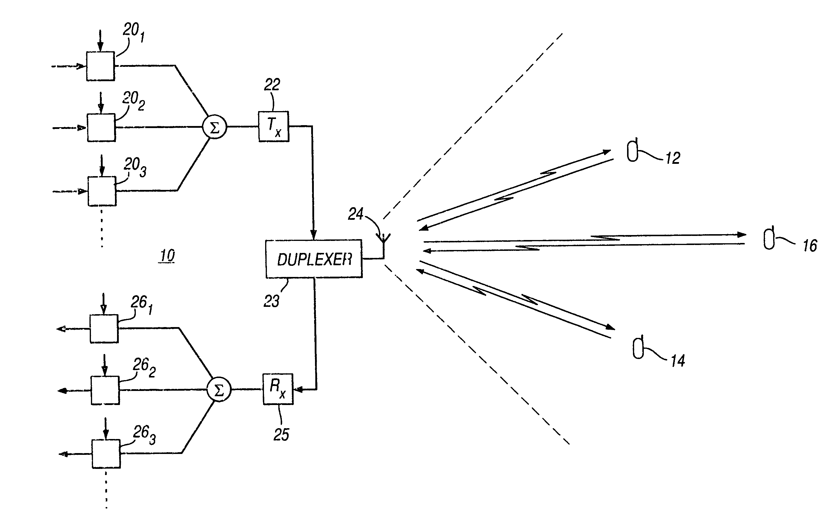
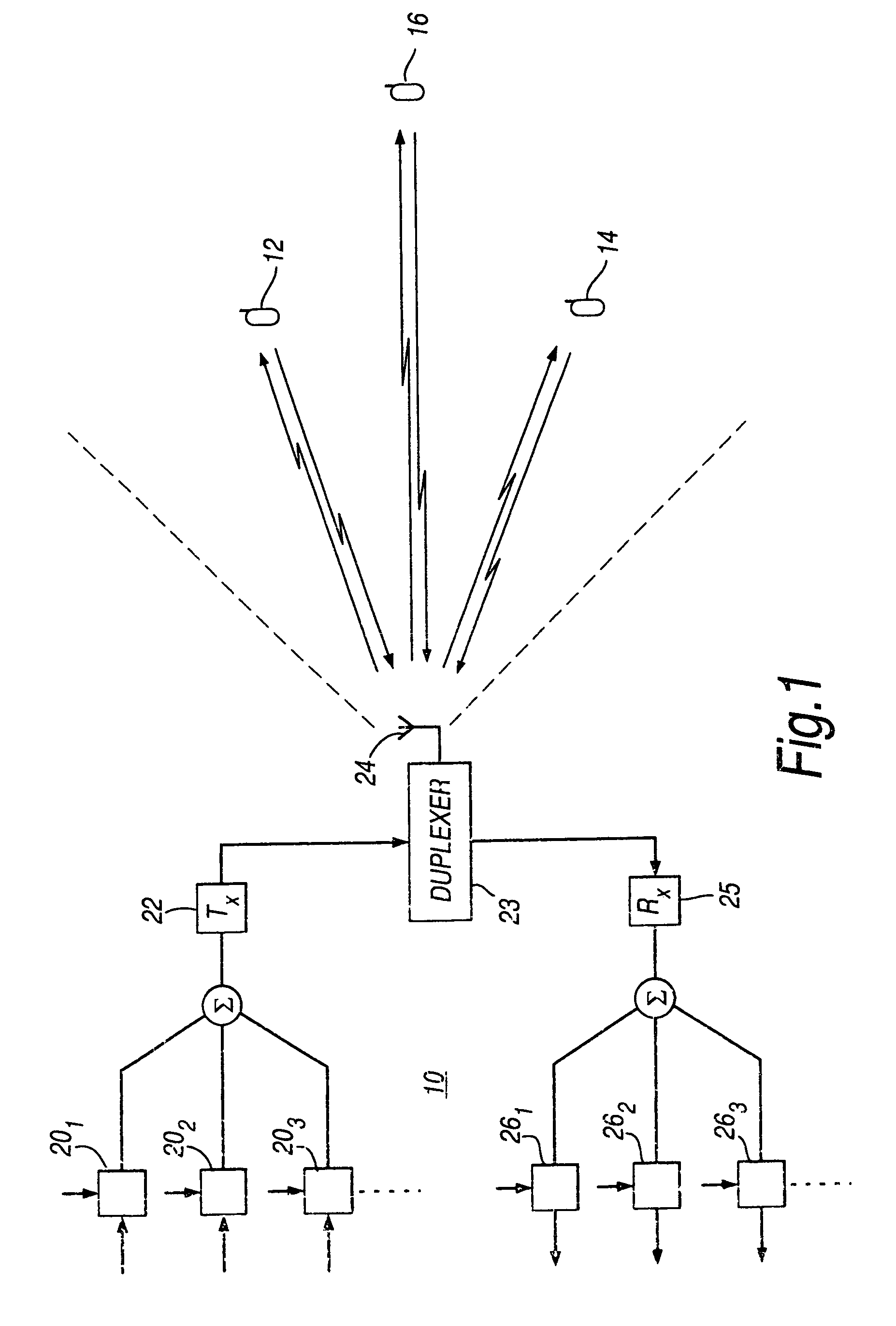
In the system described above there may still be many mobile units in a sector, which may lead to unacceptable levels of MUI.
If an attempt were made to reduce the number of mobile units in any one sector by reducing the sector size, this would lead to an increase in the number of handovers from one sector to another which would need to be performed, which would reduce the efficiency of the system.
Since the downlink and uplink transmission beams may not have the same channel characteristics, for example because different frequencies are used for t...

Method used


Image

  • Adaptive beam forming using a feedback signal
  • Adaptive beam forming using a feedback signal
  • Adaptive beam forming using a feedback signal

Examples


first embodiment

of Communication System

[0110]A mobile communication system according to a first embodiment of the present invention is shown in FIG. 6. In FIG. 6, base station 10 and mobile unit 12 cooperate to control the direction of a transmission beam 20 which is transmitted from the base station to the mobile unit. Base station 10 comprises beam former unit 30, transmitters 321, 322, 323, antenna elements 341, 342, 343, beam former control unit 36, receiving antenna 38, receiver 40 and demultiplexer 42. Mobile unit 12 comprises antenna 44, duplexer 46, receiver 48, beam separator 50, beam quality indicators (BQIs) 52, 54, 56, comparator 58, multiplexer 60 and transmitter 62.

[0111]In operation, beam former unit 30 receives a signal for transmission to mobile unit 12 and modifies the signal in accordance with a control signal from beam former control unit 36 to produce antenna signals. The operation of the beam former unit 30 is described later in detail with reference to FIG. 7. The antenna sig...

second embodiment

of Communication System

[0140]A mobile communications system according to a second embodiment will now be described with reference to FIG. 10. The second embodiment is designed to employ both transmit diversity and adaptive antenna techniques. In one kind of transmit diversity technique (referred to as antenna diversity), two or more different transmission antennas or antenna arrays are provided, and the best antenna (or antenna array) for data transmission at any given time is selected. The different antennas (or arrays) may be spaced apart at different positions or may have different orientations. In this way, if the transmission path from one of the transmitters is blocked or undergoing adverse conditions such as deep fade, the other transmitter may be used for transmission. If information about the relative quality of the signals from the two transmitters is available, instead of simply selecting one of the antennas, the system can be improved by using maximum ratio combining at ...


PUM


Abstract

Transmitting apparatus (10) for transmitting a transmission signal to a receiving apparatus (12) is described. The transmitting apparatus (10) comprises means (30, 32, 34) for transmitting to the receiving apparatus a plurality of transmission beams in accordance with a transmission beam pattern, at least one of the beams carrying the transmission signal, each beam being distinguishable from the or each other beam, means (38, 40) for receiving from the receiving apparatus a feedback signal based on measures of the quality of the transmission beams received at the receiving apparatus, and means (36) for adjusting the transmission beam pattern in dependence on the feedback signal. Corresponding receiving apparatus, and corresponding methods are also described.

Description

RELATED APPLICATIONS[0001]The present application is a 371 of PCT / JB01 / 03632 filed Aug. 14, 2001, which claims foreign priority from United Kingdom patent application number 0018859.9, filed 8 / 15 / 2000, which is incorporated by reference in its entirety, including any appendices and references thereto.BACKGROUND OF INVENTION[0002]1. Field of the Invention[0003]The present invention relates to adaptive beam forming techniques for controlling the beam pattern of a transmission beam. In particular, but not exclusively, the present invention relates to adaptive beam forming techniques for use in the downlink of a mobile cellular communications system, and to hybrid transmit diversity and adaptive beam forming techniques.[0004]2. Description of Related Art[0005]In a cellular mobile communications system, the area in which the system is to operate is divided into a plurality of cells, each of which is served by a base station. Each base station is allocated a certain number of radio freque...

Claims


Application Information

Patent Timeline
IPC IPC(8): H04B1/38G01S3/16H01Q3/22H04B7/06H04B7/10H04B7/26
CPCH04B7/0632H04B7/0617H04B7/0695
Inventor GUO, YINGJIE JAY
Owner FUJITSU LTD
Why Eureka
Try Eureka