Optical disc apparatus

a technology of optical discs and optical discs, applied in the field of optical disc apparatuses, can solve the problems of increasing the overall cost of the apparatus, the inability to maintain the stability of data recording/reproduction, and the power of the laser light, so as to reduce the amount of reflected light, and reduce the effect of reflected ligh

Inactive Publication Date: 2006-11-07
TEAC CORP
View PDF16 Cites 5 Cited by
  • Summary
  • Abstract
  • Description
  • Claims
  • Application Information

AI Technical Summary

Benefits of technology

[0014]In an example configuration of the present invention, said sampling means samples the amount of reflected light obtained immediately after irradiation of laser light at recording power. When laser light is irradiated at recording power, the amount of reflected light increases at the instant following the starting of irradiation in a brief period of time. Subsequently, a recording film is fused and sublimated by recording power, or a crystalline state of the recording film is shifted to an amorphous state so that pits are formed. The occurrence of the pits causes the amount of reflected light to decrease. Because the amount of reflected light obtained when no pits are formed depends on the inclination of the optical axis of laser light relative to the optical disc during irradiation of laser light at recording power, the amount of reflected light reaches a peak when the tilt is zero, that is, when laser light is irradiated onto the optical disc from a direction almost perpendicular to the optical disc. Accordingly, by using a level of the amount of reflected light obtained immediately after irradiation of laser light at recording power, it becomes possible to perform tilt control without influence exerted by the pits.
[0015]In another configuration of the present invention, said sampling means samples the amount of reflected light obtained when laser light is irradiated at reproducing power or erasing power. For CD-R, DVD-R or the like, laser light is irradiated at reproducing power during mark periods and space periods between the mark periods. In the space periods, the amount of reflected light is not influenced by the pits and maintains a level corresponding to the inclination of the optical axis of laser light relative to the optical disc. On the other hand, for CD-RW, DVD-RW, or the like, laser light is irradiated at erasing power during the space periods. By applying erasing power adequately, the pits which have already been formed can be deleted in spite of a certain degree of the tilt. After deletion of the pits, the amount of reflected light maintains a level corresponding to the inclination of the optical axis of laser light relative to the optical disc without influence exerted by the pits. In either case, by using the level of the amount of reflected light during the space periods, it becomes possible to perform tilt control. Here, it should be noted that when erasing power is inadequate and tilt exists, some of the pits remain not erased because the power applied to the optical disc is reduced by the tilt, with a result that the remaining pits reduces the amount of reflected light. Further, the amount of reflected light itself is decreased by the tilt. Because the action of both the remaining pits and the tilt causes the amount of reflected light to decrease, the tilt may be controlled, even when some of the pits remain not erased due to inadequate erasing power, by adjusting so as to increase the amount of reflected light.

Problems solved by technology

A recordable optical disc apparatus such as a CD-R / RW drive or a DVD-R / RW drive has a problem that stability of data recording / reproducing cannot be maintained when an optical disc tilts relative to an optical axis of laser light (in a tilt state).
Further, there is another problem that the overall cost of the apparatus is increased by providing a separate tilt sensor 54.
However, the occurrence of tilt reduces the power of the laser light incident to the optical disc surface and causes failure of forming marks due to insufficient power, with a result that reflectance is not decreased.
Accordingly, such a structure for minimizing the amount of reflected laser light may cause inaccurate control of the amount of tilt.

Method used


Image

  • Optical disc apparatus
  • Optical disc apparatus
  • Optical disc apparatus

Examples


Embodiment Construction

[0038]A preferred embodiment of the present invention will be described below while referring to the drawings.

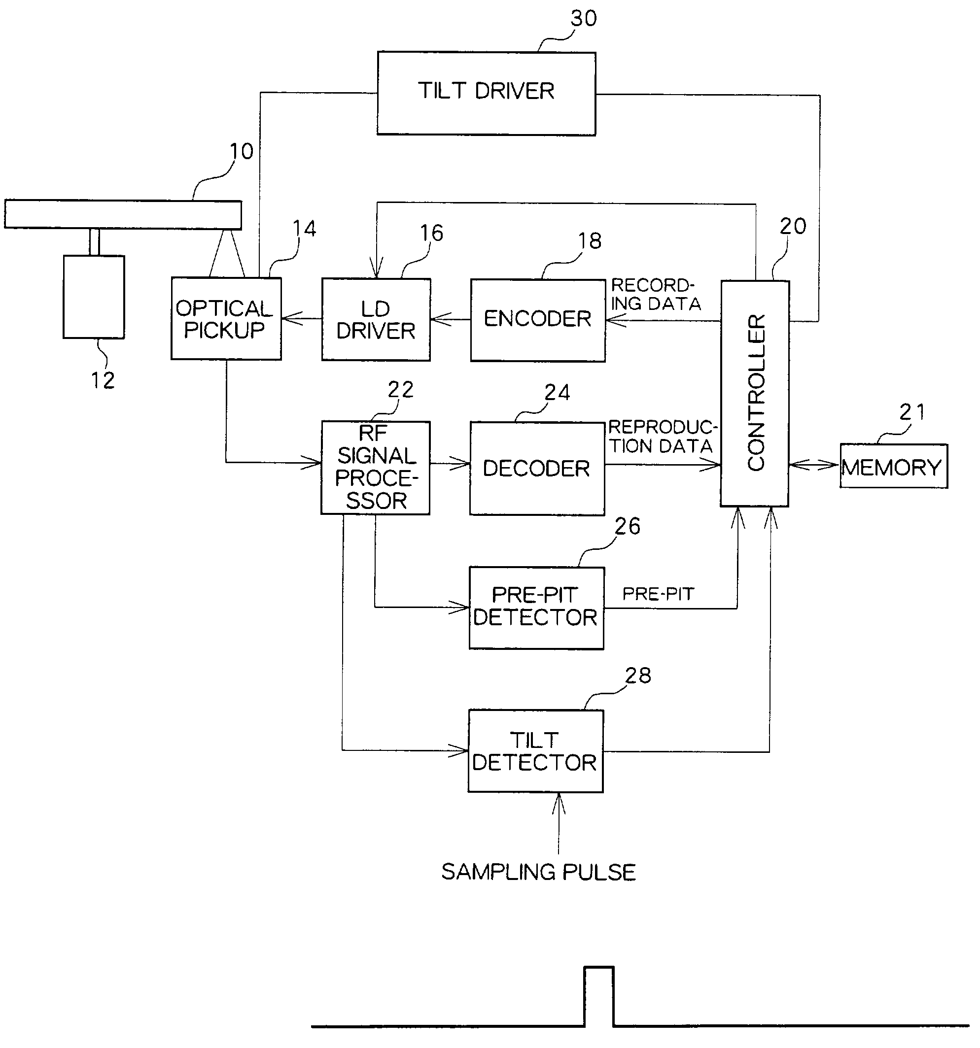
[0039]FIG. 1 is a block diagram showing a configuration of an optical disc apparatus according to the present embodiment. An optical disc 10 is driven by a spindle motor 12 to be rotated at CAV (or CLV).

[0040]An optical pickup 14 placed so as to oppose the optical disc 10 irradiates laser light at recording power onto the optical disc 10 to record data, or irradiates laser light at reproducing power onto the optical disc 10 to reproduce data. During data recording, recording data obtained from a controller 20 is modulated by an encoder 18 and converted to a driving signal at a LD driver 16 so as to drive laser diodes (LD) of the optical pickup 14. During data reproduction, the amount of reflected light is converted to an electric signal by a four-segmented photo detector in the optical pickup 14. The converted electric signal is provided to an RF signal processor 22 and pass...


PUM

PropertyMeasurementUnit
poweraaaaaaaaaa
timeaaaaaaaaaa
optical axisaaaaaaaaaa

Abstract

An optical disc apparatus in which the inclination of an optical axis of laser light relative to an optical disc is adjusted. When data is recorded, laser light is irradiated at recording power in mark periods and irradiated at reproducing power or erasing power in space periods. Immediately after the beginning of the mark periods, no pits are ye formed even though recording power is applied and the amount of reflected light has a level corresponding to the inclination of the optical axis of laser light relative to the optical disc without influence exerted by the pits. Also in the space period, the amount of reflected light has a level corresponding to the inclination of the optical axis of laser light relative to the optical disc. By sampling the reflected light signal at the instant following to the beginning of the mark period or space periods, the inclination is adjusted so as to maximize the sampled signal level.

Description

BACKGROUND OF THE INVENTION[0001]1. Field of the Invention[0002]The present invention relates to an optical disc apparatus, and more particularly to an adjustment to the inclination (tilt) of an optical disc relative to an optical axis of laser light.[0003]2. Description of the Related Art[0004]A recordable optical disc apparatus such as a CD-R / RW drive or a DVD-R / RW drive has a problem that stability of data recording / reproducing cannot be maintained when an optical disc tilts relative to an optical axis of laser light (in a tilt state). Accordingly, a technology for providing a tilt sensor to the optical disc to detect the amount of tilt and adjusting the inclination of an optical pickup according to the detected amount of tilt has been proposed.[0005]A block diagram of an optical disc apparatus with a tilt sensor is outlined in FIG. 10. An optical disc 10 is driven by a spindle motor 12 to be rotated. An optical pickup 14 is placed so as to be opposed to the optical disc 10. Lase...

Claims


Application Information

Patent Timeline
Patent Type & Authority Patents(United States)
IPC IPC(8): G11B7/00G11B7/095G11B7/0045G11B7/006G11B21/02
CPCG11B7/0062G11B7/0956G11B7/00456G11B7/095
Inventor TAKEDA, NAOTO
Owner TEAC CORP
Why Eureka
Try Eureka