Logarithmic light intensifier for use with photoreceptor-based implanted retinal prosthetics and those prosthetics

a technology of retinal prosthetics and logarithmic light intensifiers, which is applied in the field of retinal prosthetics, can solve the problems of unsuitable use for blind individuals with implanted retinal prosthetics, insufficient light power, and inability to arbitrarily increase light amplitude, so as to maximize electrical stimulation of retinal nerves or cells, enhance retinal prosthetic performance, and avoid damage.

Inactive Publication Date: 2006-11-07
SECOND SIGHT MEDICAL PRODS
View PDF4 Cites 19 Cited by
  • Summary
  • Abstract
  • Description
  • Claims
  • Application Information

AI Technical Summary

Benefits of technology

[0009]The present invention is directed to a method and apparatus for providing enhanced retinal prosthetic performance. More particularly, the invention is directed to a light amplifier and electrical circuitry for driving an implanted ret

Problems solved by technology

However, they appear unsuitable for use by blind individuals with implanted retinal prosthetics of the photoreceptor-electrode kind.
It would seem that they do not provide enough light power.
Moreover, l

Method used


Image

  • Logarithmic light intensifier for use with photoreceptor-based implanted retinal prosthetics and those prosthetics
  • Logarithmic light intensifier for use with photoreceptor-based implanted retinal prosthetics and those prosthetics
  • Logarithmic light intensifier for use with photoreceptor-based implanted retinal prosthetics and those prosthetics

Examples


second embodiment

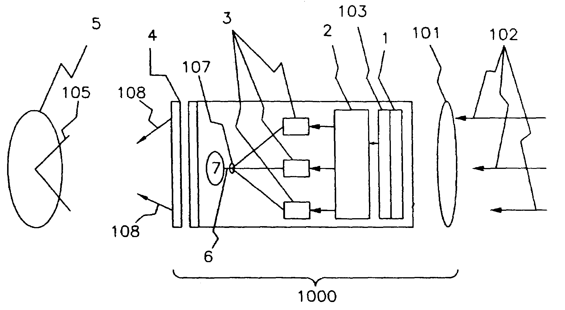
[0052]A shutter (4) is part of the The shutter (FIG. 1, (4)) is of a mechanical design (old in the art), or an electronic shutter (4) (old in the art) or an electro-optical shutter (4) (old in the art). The shutter (4) cuts off light from the logarithmic light amplifier (1000) to the pupil (105) of the eye (5). This decreases the total time that light strikes the photoreceptors (FIG. 3a, (13), (14)), (FIG. 3b, 303) Consequently, the time during which the bipolar, or similar cells, are stimulated is decreased. Because the eye is not functioning as originally intended, the bipolar, or similar, cells are thought to need this “down-time” to continue to function properly.

[0053]An aspect of this invention is the use of two or more wavelengths to allow balanced biphasic stimulation with no net charge injection into the eye. As long as a biphasic type of electrical stimulation, where equal amounts of positive charge and negative charge in the form of ionic carriers or electrons or other ch...

fourth embodiment

[0057]A fourth embodiment is that of the logarithmic light amplifier (1000) itself, without any special implantable photoreceptors. This last embodiment may require a low duty cycle when used with photoreceptors (FIG. 8, (81)) connected to an electrode (82) without any electronics. It relies upon the intrinsic capacitance of an oxidizable electrode, which acquires capacitance with the buildup of an insulating oxidized layer toward the ionizable fluid present in the eye as vitreous fluid, or fluid directly associated with the eye.

[0058]In a first set of embodiments, the addition of a shutter (FIG. 1, (4)) with an off time of from 0.5 ms to 10 ms, most preferably 2 ms provides a mechanism to provide that off time (FIG. 4, (47), (48)). However, in a second set of embodiments, the time each laser is on can be controlled by electronic means (old in the art) within the laser to provide equal positive pulses and negative pulses, i.e., equal with respect to total signed charge introduced in...


PUM


Abstract

This invention is for directly modulating a beam of photons onto the retinas of patients who have extreme vision impairment or blindness. Its purpose is to supply enough imaging energy to retinal prosthetics implanted in the eye which operate essentially by having light (external to the eye) activating photoreceptors, or photo-electrical material. The invention provides sufficient light amplification and does it logarithmically. While it has sufficient output light power, the output light level still remains at a safe level. Most preferred embodiments of this invention provide balanced biphasic stimulation with no net charge injection into the eye. Both optical and electronic magnification for the image, as for example, using an optical zoom lens, is incorporated. Otherwise, it would not be feasible to zoom in on items of particular interest or necessity. Without proper adjustment, improper threshold amplitudes would obtain, as well as uncomfortable maximum thresholds. Therefore, to adjust for these, a way of proper adjustment for the threshold amplitudes and maximum comfortable thresholds is provided. Furthermore, to the extent that individual stimulation sites in the retina give different color perceptions, upon stimulation, then colors of the viewed scene is correlated with specific stimulation sites to provide a certain amount of color vision.

Description

CROSS REFERENCE TO RELATED APPLICATIONS[0001]This application is a division of U.S. patent application No. 09 / 515,383, Filed Feb. 29, 2000, now U.S. Pat. No. 6,507,758.[0002]This application claims the benefit of U.S. Provisional Application No. 60 / 125,875, filed Mar. 24, 1999.FIELD OF THE INVENTION[0003]This invention, relates generally to retinal prosthetics and more particularly to a method and apparatus for enhancing retinal prosthetic performance.[0004]This invention relates to directly modulating a beam of photons of sufficient energy onto retinal prosthetic implants of patients who have extreme vision impairment or blindness.BACKGROUND OF THE INVENTION[0005]A healthy eye is has photosensitive retinal cells (e.g. rods and cones) which react to specific wavelengths of light to trigger nerve impulses. Complex interconnections among the retinal nerves assemble these impulses which are carried through the optic nerve to the visual centers of the brain, where they are interpreted. ...

Claims


Application Information

Patent Timeline
IPC IPC(8): A61N1/18A61F9/007A61F2/14A61F2/48A61N1/36
CPCA61F9/08A61N1/36046
Inventor GREENBERG, ROBERT J.SEIDMAN, ABRAHAM N.SCHULMAN, JOSEPH H.
Owner SECOND SIGHT MEDICAL PRODS
Why Eureka
Try Eureka