Off-pitch column redundancy using dynamic shifters

a column shifter and column shift technology, applied in the field of fault-tolerant memory devices, can solve the problems of increased labor intensity, increased labor intensity, and increased production costs of semiconductor devices, and achieve the effect of improving the memory redundancy design and improving the efficiency of the column redundancy schem

Active Publication Date: 2006-11-07
ORACLE INT CORP
View PDF16 Cites 42 Cited by
  • Summary
  • Abstract
  • Description
  • Claims
  • Application Information

AI Technical Summary

Benefits of technology

[0008]Broadly speaking, the present invention is a method and apparatus provides an improvement in memory redundancy design by providing for off-pitch column shifting during data read and write operations to a memory array. In a selected embodiment, the shift position is dynamically updated every access cycle, based upon the block of the memory array being accessed. A shifter circuit located outside of the memory sub-blocks may be used to keep track of the bad addresses by comparing a read or write memory address to the bad address and deciding where to shift the address data to thereby implement an improved and efficient column redundancy scheme.

Problems solved by technology

As memory size, density and complexity increase, there are more opportunities for physical and circuit defects in the constructed integrated circuits, which can lower the production yield of semiconductor devices.
Typically, information identifying a defective element is stored in latches or fuses located on each column or row of data path, though this requires excessive space in the valuable memory array area.
As microprocessors become more and more sophisticated (such as with 32-bit or 64-bit data path processors), additional problems arise, particularly when such devices use memories having multiple arrays.
For example, a single redundant set of arrays cannot compensate for a short defect between arrays belonging to two adjacent main memory arrays.
Additionally, data transmissions along the redundant path can suffer a speed penalty due to the extra line length and the incidence of higher parasitic capacitance.
Variable delays from data paths are highly undesirable in high-performance memory storage, as they force the performance of an entire memory array to be no better than that of the extended length path's performance.
An increase in the register count creates other problems, including reduced array efficiency, reduced redundancy register yield and cosmic ray protection issues.

Method used


Image

  • Off-pitch column redundancy using dynamic shifters
  • Off-pitch column redundancy using dynamic shifters
  • Off-pitch column redundancy using dynamic shifters

Examples


Embodiment Construction

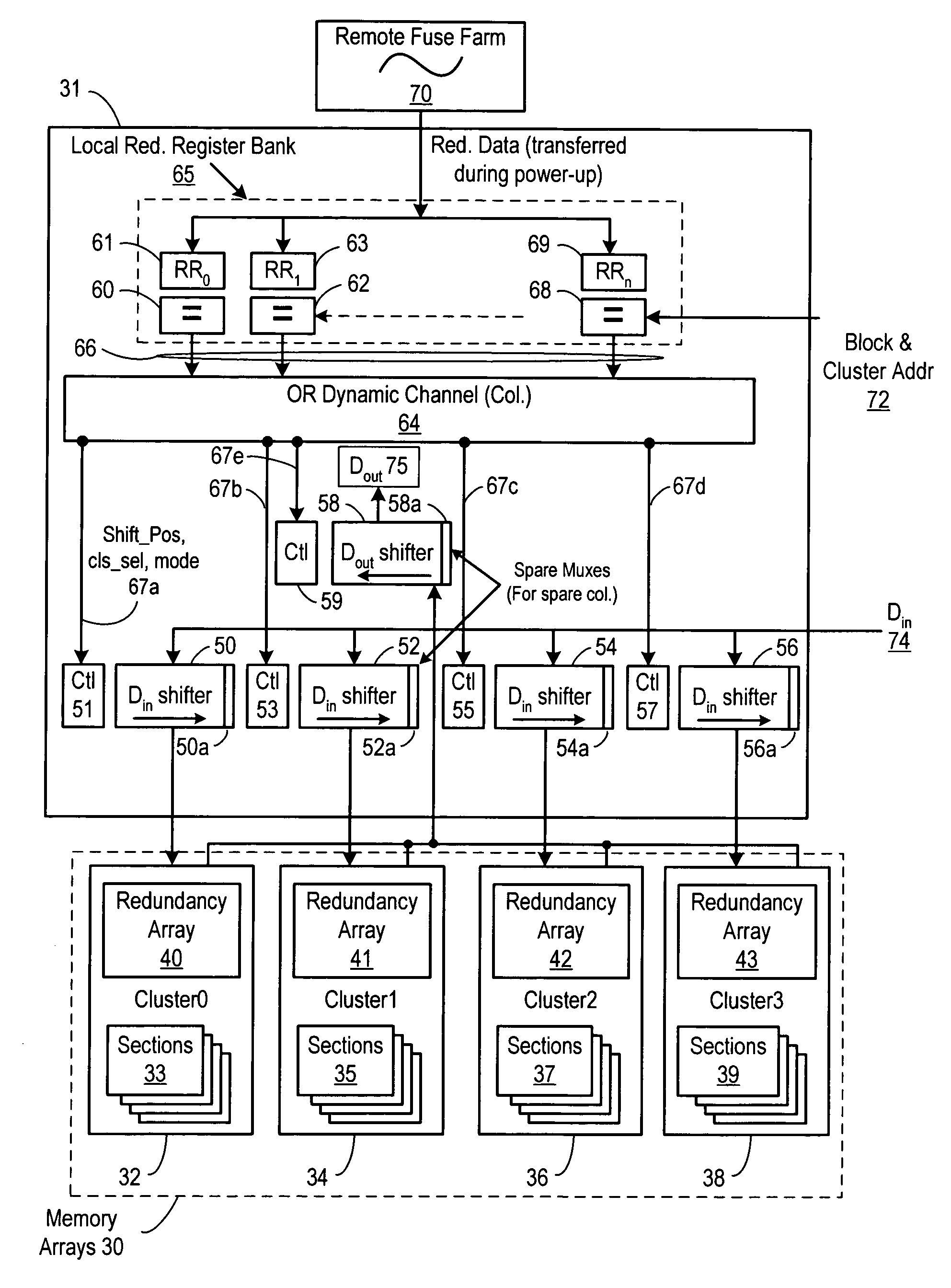
[0014]A method and apparatus for providing off-pitch column redundancy using dynamic shifters is described. While various details are set forth in the following description, it will be appreciated that the present invention may be practiced without these specific details. For example, selected aspects are shown in block diagram form, rather than in detail, in order to avoid obscuring the present invention. Some portions of the detailed descriptions provided herein are presented in terms of algorithms or operations on data within a computer memory. Such descriptions and representations are used by those skilled in the field of memory design to describe and convey the substance of their work to others skilled in the art. In general, an algorithm refers to a self-consistent sequence of steps leading to a desired result, where a “step” refers to a manipulation of physical quantities which may, though need not necessarily, take the form of electrical or magnetic signals capable of being ...


PUM


Abstract

An apparatus and method for controlling and providing off-pitch shifting circuitry for implementing column redundancy in a multiple-array memory is described in connection with an on-board cache memory integrated with a microprocessor. Depending upon the particular sub-array being accessed, shift position data is provided to a shared, off-pitch shift circuit to control the read and/or write operations for the memory. A register bank stores data identifying the defective columns which is compared to the incoming address information to detect any matches. In response to a match, control information is provided to the off-pitch shift circuit for shifting or re-routing the incoming data to a non-defective address in the memory. In this way, defective columns located in different positions in each sub-array can be replaced by redundant paths, thereby repairing the cache and increasing the manufacturing yield of microprocessors with an on-board cache memory.

Description

BACKGROUND OF THE INVENTION[0001]1. Field of the Invention[0002]The present invention relates generally to the field of fault tolerant memory devices. In one aspect, the present invention relates to a column redundancy method and system using off-pitch column shifting in connection with a semiconductor memory device.[0003]2. Description of the Related Art[0004]Computer systems are constructed of many components, typically including one or more processors that are connected to a motherboard for access to one or more memory devices, (such as RAM) and secondary storage devices (such as hard disks and optical discs). For example, FIG. 1 is a diagram illustrating a multiprocessor system 10 with multiple memories. Generally, a processor 1a connects to a system bus 12. Also connected to the system bus 12 is a memory (e.g., 14a). During processor operation, CPU 2 processes instructions and performs calculations. Data for the CPU operation is stored in and retrieved from memory using a memor...

Claims


Application Information

Patent Timeline
Patent Type & Authority Patents(United States)
IPC IPC(8): G11C29/00
CPCG11C29/808G11C29/848G11C29/802
Inventor KAUSHIK, PRADEEPWENDELL, DENNISSESHADRI, SURESH
Owner ORACLE INT CORP
Why Eureka
Try Eureka