Chipper knife and holder therefor

a chipper knife and holder technology, applied in the field of chipper knives, can solve the problems of inability to regrind worn chipper knives without time-consuming handling, often becomes too expensive, and the physical properties of chipper knives often set lower limits as regards the size of the flank, so as to reduce operative expenses, improve chip quality, and increase the yield of timber

Inactive Publication Date: 2006-11-14
IGGESUND TOOLS
View PDF6 Cites 8 Cited by
  • Summary
  • Abstract
  • Description
  • Claims
  • Application Information

AI Technical Summary

Benefits of technology

[0008]The present invention aims at providing a chipper knife which eliminates, or at least reduces, the drawbacks of prior-art chipper knives of the type mentioned by way of introduction. In particular, the invention aims at providing a chipper knife which gives a higher chip quality, an increased timber yield and reduced operative expenses by being able to cut chips of high and uniform quality while limiting the amount of oversized chips and the amount of fine material in the form of splinters and chips, and by the material volume of the chipper knife being reduced while maintaining high strength. At least these objects are achieved by means of a chipper knife according to claim 1.
[0010]The invention is thus based on the understanding that the above-mentioned objects can be achieved by a chipper knife whose main surface facing the wood side of the chipper knife has a cross-sectionally convexly bent surface portion that connects to and extends backwards from the flank and has a length amounting to at least 20% of the total cross-sectional length of the chipper knife. Such a design of the chipper knife makes it possible to form a chipper knife with tapering cross-sectional dimensions in the direction of its terminal edges, i.e. also in the area of the flank, while the heavily loaded cross-sections in the intermediate portion of the chipper knife can be given a dimension that is large enough to handle the strain to which it is subjected. Consequently, as already mentioned, the chipper knife can, be designed with a small and material-saving cross-sectional area. In addition, a convexly bent surface portion gives the possibility of forming the seats of the holder in such a manner that the chipper knife is safely retained in the holder in a distinct and well-defined position without any risk of unintentional incorrect fitting or displacement of position as a consequence of the forces acting on the chipper knife. In other words, positive engagement is obtained between the chipper knife and the seats of the holder in contrast to frictional engagement which is common in this type of installation.
[0020]In the preferred embodiment, each of the convexly bent surface portions, at one of its ends, abuts on a flank which suitably can be plane or, for instance, slightly bent, and at its other end, on a chip guiding portion comprising a bead that guides the cut chips outwards and away from the holder to which the chipper knife is attached, in order to reduce the wear and tear on the holder and prevent penetration of wood fibres between the chipper knife and an inner clamping piece of the holder. However, the chip guiding portion of the chipper knife could also be formed in many other ways, for instance, without a chip guiding bead.
[0021]According to the preferred embodiment of the chipper knife, there are many advantages of the inventive design. Since the convexly bent surface portions on each main surface are offset relative to one another and overlap one another, it is possible to form the chipper knife with an essentially smaller cross-sectional area than the corresponding chipper knife with plane main surfaces because it can be given a cross-sectional shape tapering towards its ends, but all the same give the critical and heavily loaded cross-sections in the intermediate portion of the chipper knife a greater cross-sectional dimension and, thus, improved strength. On the contrary, since the convexly bent surface portions drop towards their respective ends, the cross-sectional length of the flank of the chipper knife can be reduced considerably relative to the corresponding chipper knife with plane main surfaces. As already mentioned, this gives the chipper knife improved operation characteristics and makes it possible to produce chips of a higher quality and with a greater yield of wood. In addition, a chipper knife formed according to the present invention has the further advantage of facilitating the positioning of the chipper knife in the holder since, in practice, there is only one distinct position it can take in the holder.

Problems solved by technology

Producing chipper knives with such a complicated shape of the flank is technically possible but, in practice, it usually becomes too expensive.
However, the physical properties of the chipper knife often set lower limits as regards how small the flank can be made since the chipper knife has to have a predetermined minimum cross-sectional thickness in order to resist the strain to which it is exposed.
However, in such a knife system, it is not feasible to regrind worn chipper knives without time-consuming handling since this implies that their position in the holder is changed after regrinding, but instead the worn chipper knives are discarded.
However, this cannot be easily achieved since the chipper knife for reasons of function and strength of material needs to have a certain size and, especially, a minimum thickness in certain cross-sections subjected to heavy loads.

Method used


Image

  • Chipper knife and holder therefor
  • Chipper knife and holder therefor
  • Chipper knife and holder therefor

Examples


Embodiment Construction

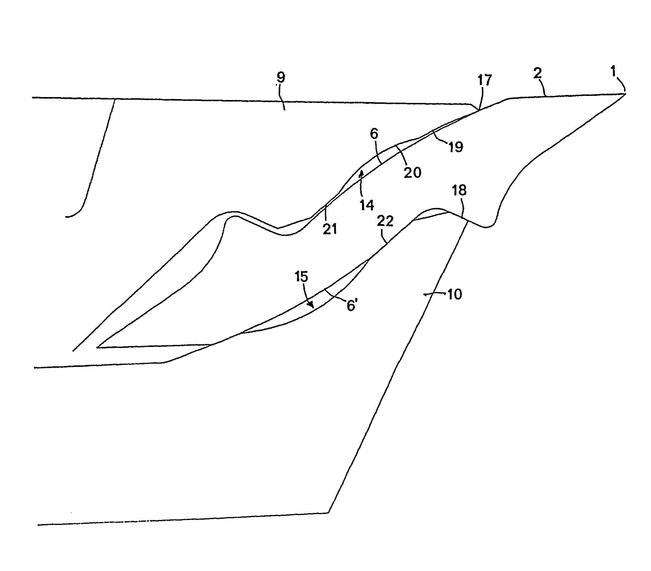
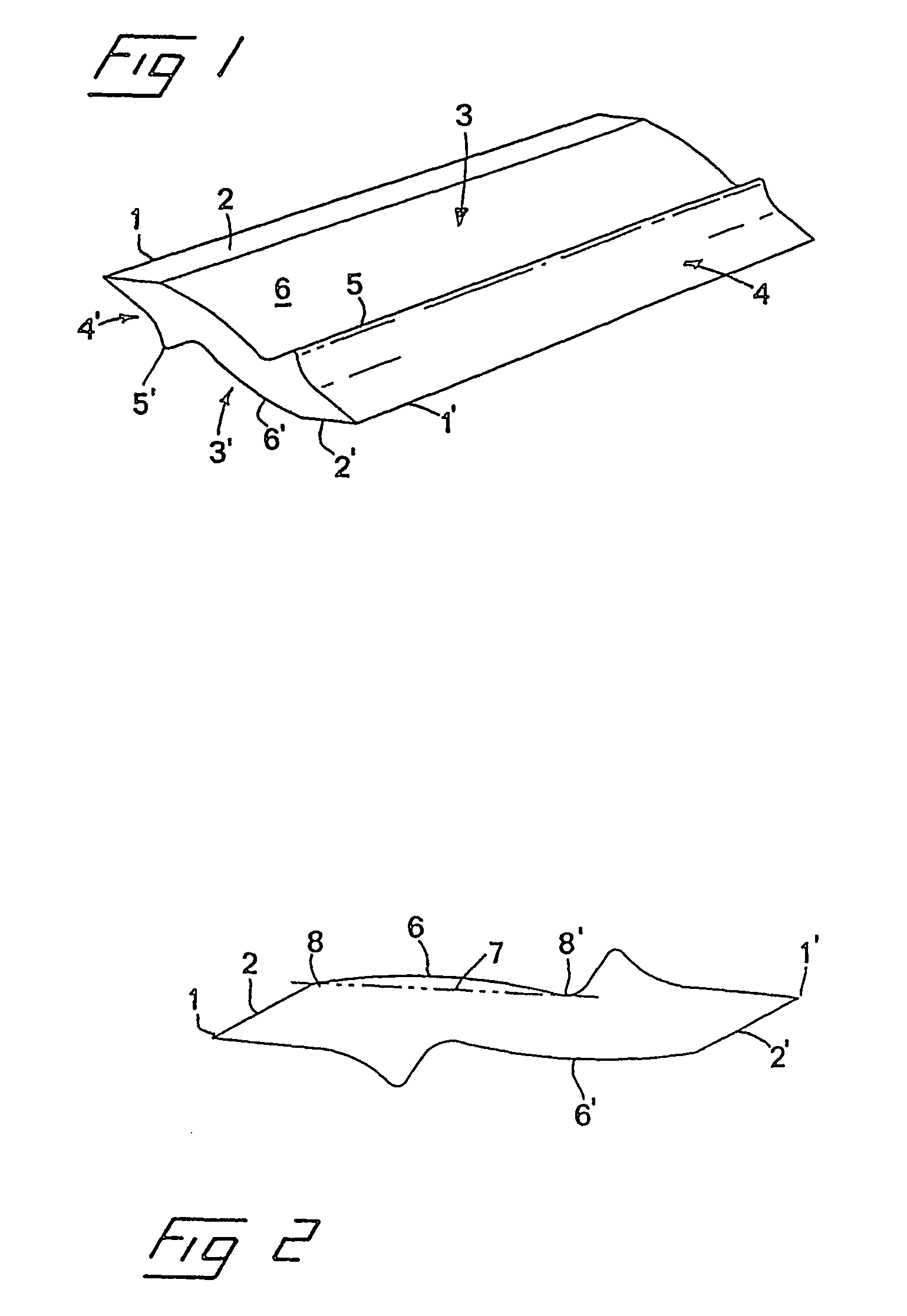
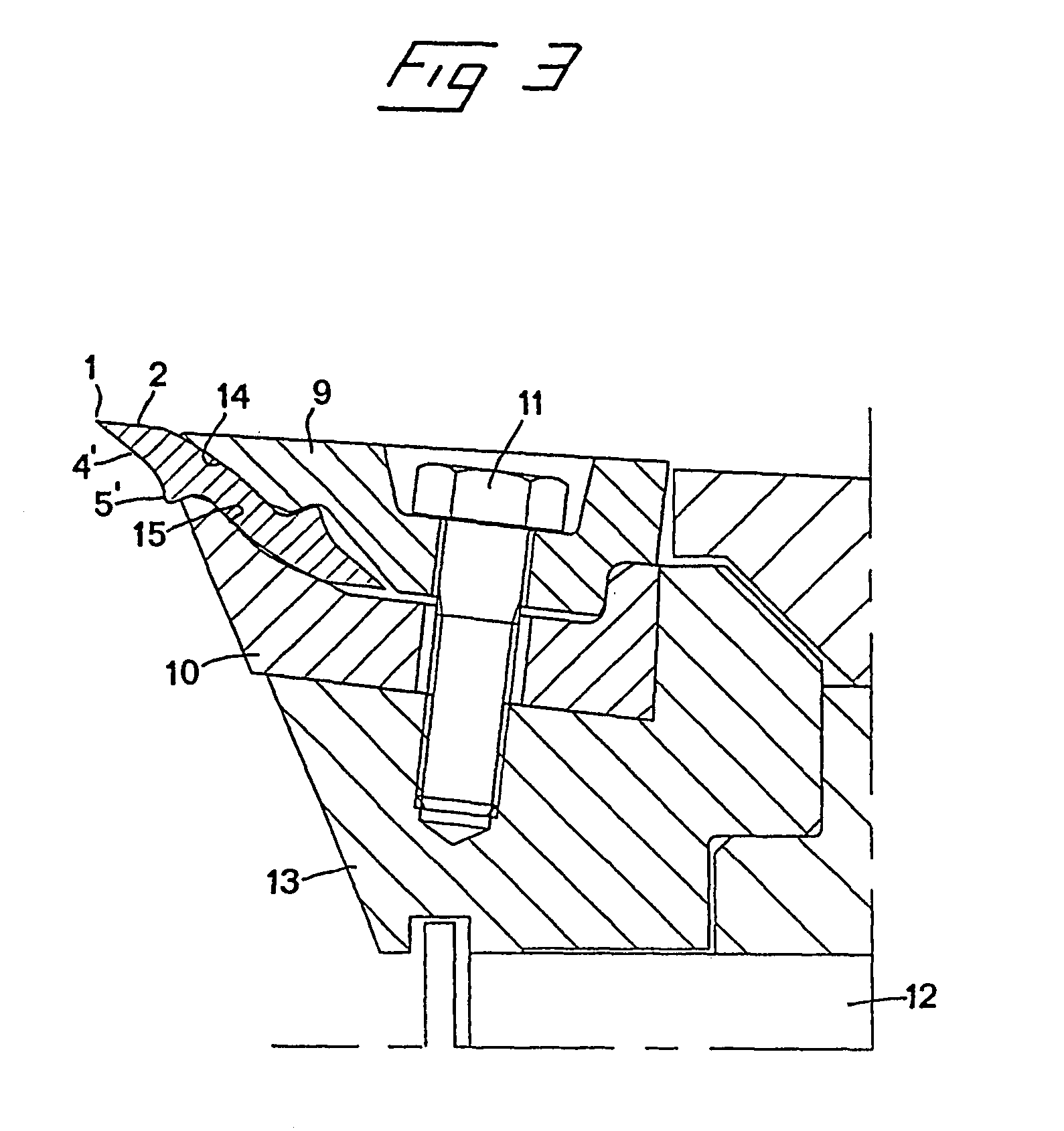
[0032]FIGS. 1 and 2 show a first preferred embodiment of a chipper knife according to the present invention, on the one hand in a perspective view and, on the other, in cross-section. The chipper knife is of an indexable insert type having two cutting edges 1, 1′ and having cross-sectional point symmetry about a central point. On each side of a straight line between the cutting edges, the chipper knife has a flank 2, 2′, a main surface 3, 3′ and a chip guiding surface 4, 4′. Between the respective main surfaces 3, 3′ and the corresponding chip guiding surface, the chipper knife is formed with a chip guiding bead 5, 5′.

[0033]Each main surface 3, 3′ comprises a cross-sectionally convexly bent surface portion 6, 6′. In the preferred embodiment, the bent surface portions have a part-circular shape in cross-section, and in FIG. 2 a straight line 7 is drawn forming a chord which connects the outer edges or ends 8, 8′ of the part-circularly bent surface portion.

[0034]As is evident from the...


PUM

PropertyMeasurementUnit
lengthsaaaaaaaaaa
cross-sectional lengthaaaaaaaaaa
symmetryaaaaaaaaaa

Abstract

The invention relates to a chipper knife for chippers of the type comprising a tool (12) which is rotatable on an axis of rotation and is in the form of, for example a drum, disc or truncated conical body, which supports a plurality of such chipper knives. The chipper knife comprises at least one cutting edge (1) which is formed between a flank (2, 2′) and a chip guiding surface (4, 4′), and two opposite main surfaces (3, 3′) which are adapted to abut against and be retained on the opposite seats (14, 15) of a holder (9, 10) on the tool. At least one main surface (3, 3′) of the chipper knife which is located on a wood side of the chipper knife comprises a cross-sectionally convexly bent surface portion (6, 5′) which connects to and extends backwards from the flank (2, 2′) and the chord of which constitutes at least 20%, preferably at least 30% and, most preferably, at least 40% of the total cross-sectional length of the chipper knife. The invention also relates to a holder for such a chipper knife.

Description

FIELD OF THE INVENTION[0001]The present invention relates to a chipper knife for chippers of the type comprising a tool which is rotatable on an axis of rotation and is in the form of, for example, a drum, disc or truncated conical body, which supports a plurality of such chipper knives in order to cause, during rotation of the tool, chipping of pieces of wood which are fed to the same, the chipper knife comprising at least one cutting edge which is formed between a flank and a chip guiding surface, and two opposite main surfaces which are adapted to abut against and be retained on opposite seats of a holder on the tool.[0002]The invention also relates to a holder for such chipper knives according to the preamble to claim 13.BACKGROUND OF THE INVENTION[0003]A plurality of demands which are often contradictory are made on chippers. The most important demand is that the chipper must be able to produce wood chips of a quality that is as high and uniform as possible. Among other things ...

Claims


Application Information

Patent Timeline
Patent Type & Authority Patents(United States)
IPC IPC(8): B02C18/18B27L11/00
CPCB27L11/005Y10T407/13Y10T83/9319
Inventor BILLER, SVEN-OLOFGRANSTR M, OLOVENGELL, MATS
Owner IGGESUND TOOLS
Why Eureka
Try Eureka