
Digital television receiver and method of controlling antenna of the same

antenna controller technology, applied in the direction of ghz frequency transmission, selective content distribution, television systems, etc., can solve the problems of plurality of multi-paths and frequency obstacles, the inability to apply an antenna to a digital television receiver in public, and the inconvenience of large size and installment, so as to reduce the cost of the product, prompt judgment, and simple hardware

Inactive Publication Date: 2006-11-14
LG ELECTRONICS INC
View PDF9 Cites 30 Cited by
  • Summary
  • Abstract
  • Description
  • Claims
  • Application Information

AI Technical Summary

Benefits of technology

[0015]Another object of the present invention is to provide an antenna for a digital television receiver, controller and controlling method of the same enabling to construct the antenna with a simple hardware so as to reduce a product cost.
[0016]A further object of the present invention is to provide an antenna for a digital television receiver, controller and controlling method of the same having a prompt judgment and high reliance.
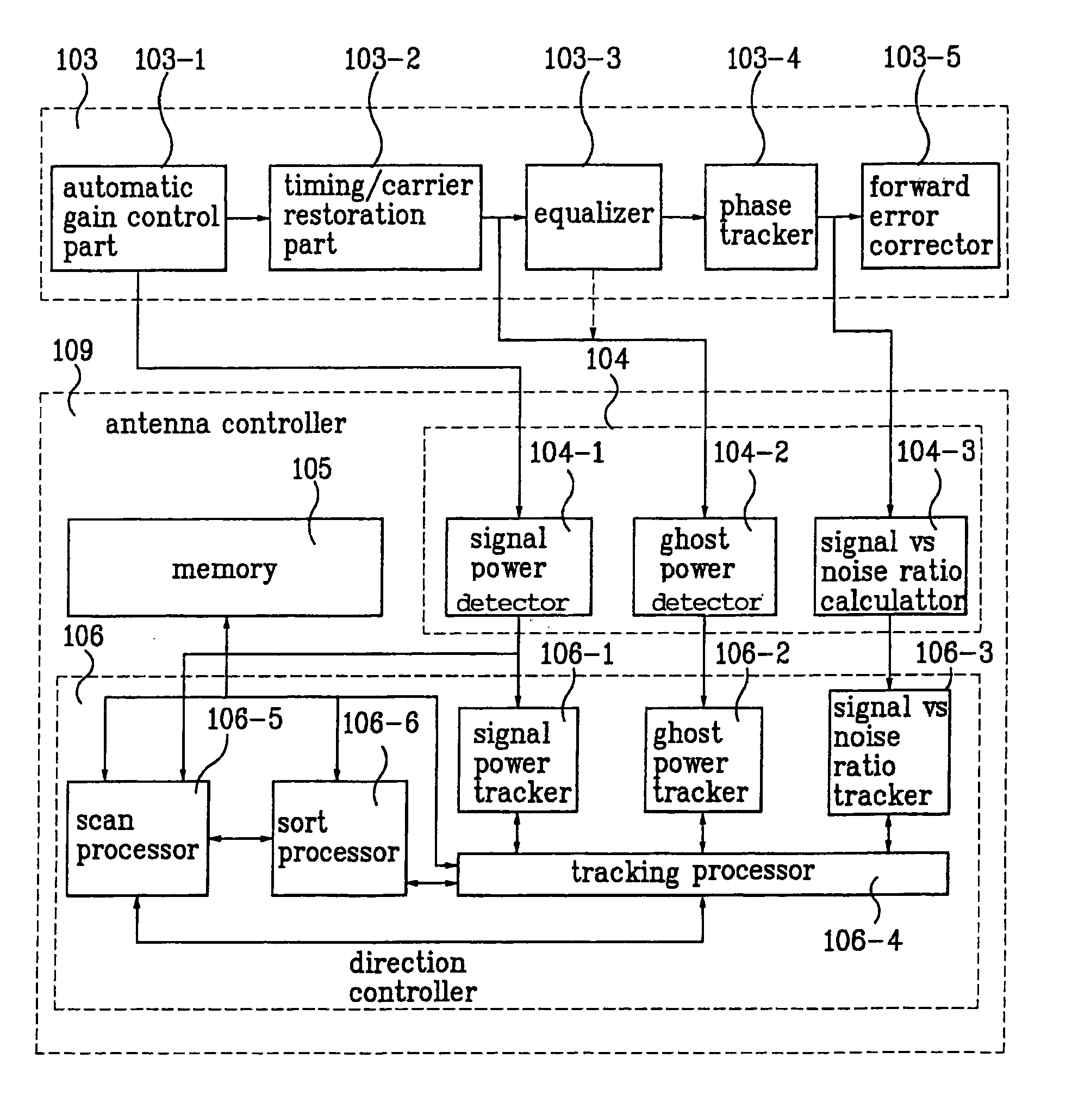
[0018]In order to attain the objectives, an antenna controller of a digital television receiver according to the present invention is constructed with digital control parts and operated separately and independently from the digital television receiver and extracts channel information from a receive chip only without using additional hardware. Moreover, an antenna controller of a digital television receiver according to the present invention attains channel information for controlling an antenna from an automatic gain controller as an initial step in a demodulation part of a digital television receiver, a data segment synchronizer as a middle step, an equalizer as a terminal step, and an SNR calculator step by step. Further, the antenna is controlled to maintain an optimal state using the extracted information. Accordingly, an apparatus and method according to the present invention enables to optimize the antenna of the digital television receiver at a severely-varying channel environment of the terrestrial microwave all the time and further improve the performance of the digital television receiver.

Problems solved by technology

Yet, no antenna applied to a digital television receiver has been introduced in public, and further has been commercialized.
First, there is a general outdoor antenna having a benefit of high receive performance but having defects such as large size and installment inconvenience.
Second, there is an indoor antennal having benefits of small size and installment convenience but defects such that a viewer has to adjust a direction of the antenna by monitoring a screen in direct when a receive sensitivity is reduced.
Besides, a plurality of multi-paths and frequency obstacles have a chance to exist in the terrestrial channels in the digital television broadcasting.
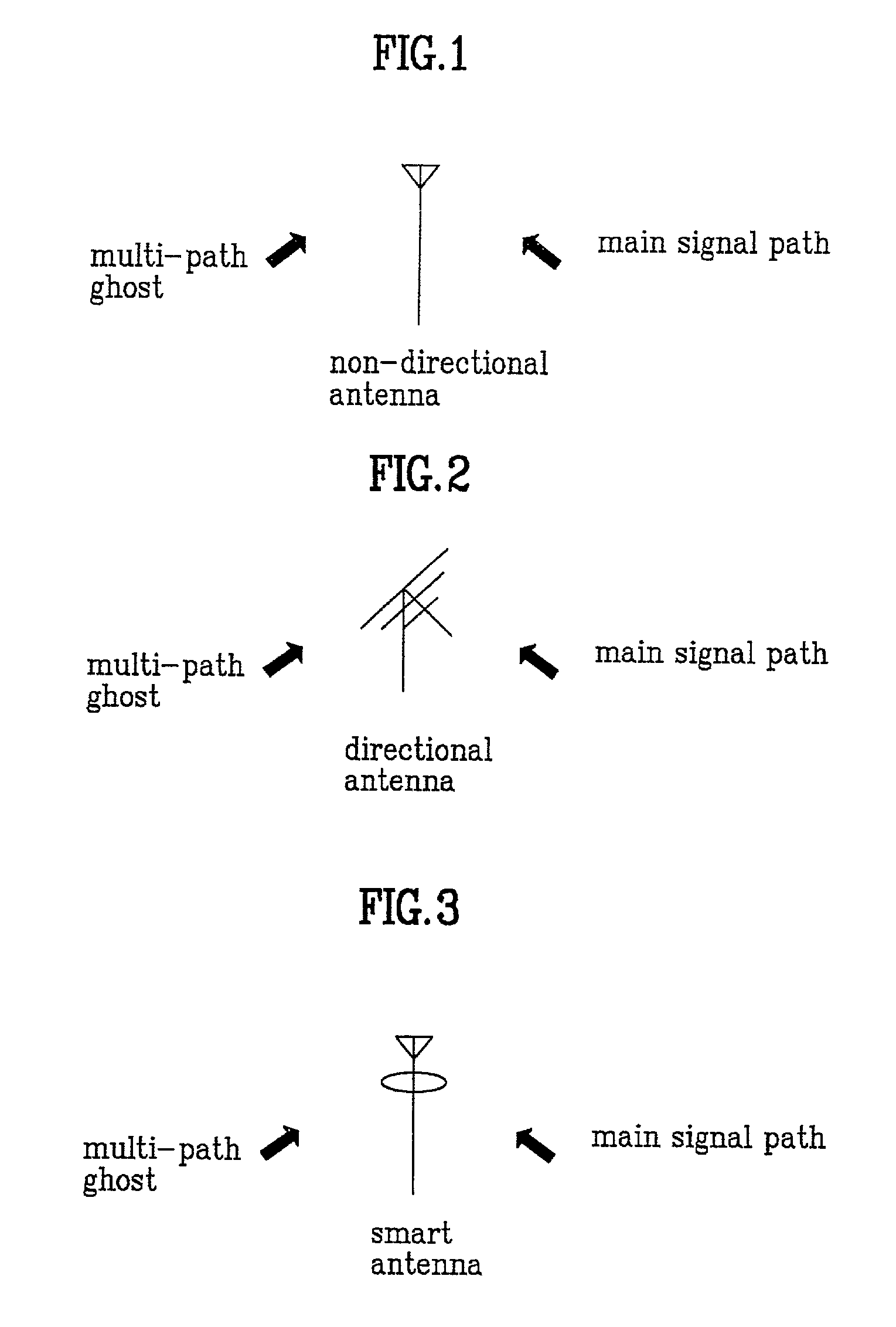
Yet, the television receiver in FIG. 1 fails to easily receive the wanted channel in the channels where the main signal is weak and the signals in the multi-paths are strong through indoor antennas, downtown-building-area antennas and the like, thereby reducing the performance of the digital television receiver.
Yet, the main signal may be blocked by the moving obstacles against radio waves under the circumstance that states of the channels vary severely.
In this case, it is difficult for the antenna to receive the main signal from other directions, whereby the performance of the digital television receiver is reduced as well.

Method used


Image

  • Digital television receiver and method of controlling antenna of the same
  • Digital television receiver and method of controlling antenna of the same
  • Digital television receiver and method of controlling antenna of the same

Examples


Embodiment Construction

[0047]Reference will now be made in detail to the preferred embodiments of the present invention, examples of which are illustrated in the accompanying drawings.

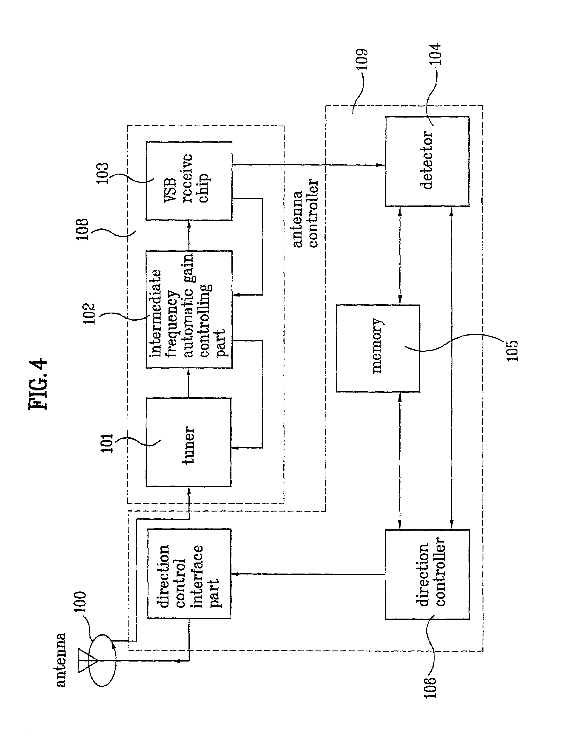
[0048]FIG. 4 illustrates a construction diagram of a digital television receiver having an antenna and a controller of the antenna according to the present invention. FIG. 4 is mainly constructed with a channel signal processing part 108 of a digital television receiver and an antenna controller 109.

[0049]Referring to FIG. 4, the channel signal processing part 108 of the digital television receiver is constructed with a tuner 101 tuning a wanted channel signal among channel signals received through an antenna 100(a smart antenna is used in this embodiment of the present invention but various other antennas may be realized in this embodiment) present of the digital television receiver, an intermediate frequency automatic gain controlling part 102 adjusting an intermediate frequency IF gain of the channel signal tuned by the t...


PUM


Abstract

Disclosed is an antenna controller of a digital television receiver and a controlling method thereof including an antenna receiving channel signals of digital television broadcasting and having a directionality dependent on a control signal, a signal processing part tuning a wanted channel signal from the channel signals and processing the tuned channel signal as a wanted form, a detection part detecting state signals of the channel signal outputted from the signal processing part, a memory, when every new state signal is detected, storing the detected new state signal sorted with previously-detected state signals, a control part producing the control signal corresponding to an optimal direction of the antenna by comparing the new state signal to the previous state signals, and an interface part providing the antenna with the control signal, thereby enabling to increase the integration of the receiver.

Description

BACKGROUND OF THE INVENTION[0001]1. Field of the Invention[0002]The present invention relates to a digital television receiver and method of controlling an antenna of the same, and more particularly, to an antenna controller of a digital television receiver and a controlling method thereof.[0003]2. Background of the Related Art[0004]VSD (Vestigial Side Band) has been chosen as a standard form for transmitting a terrestrial microwave channel in digital television broadcasting. Thus, concepts and ideas have been made to propose the early-stage antennas for a VSB receiver, and ATSC prepares the standardization of the VSB antennas. Yet, no antenna applied to a digital television receiver has been introduced in public, and further has been commercialized.[0005]Generally, antennas able to be used for digital television receivers are mainly divided into two categories.[0006]First, there is a general outdoor antenna having a benefit of high receive performance but having defects such as lar...

Claims


Application Information

Patent Timeline
Patent Type & Authority Patents(United States)
IPC IPC(8): H04N5/44H01Q1/24
CPCH01Q1/247H04N5/4401H04N21/42692H04N21/4383H04N21/44209H04N21/426H04N5/44
Inventor LEE, TAE WON
Owner LG ELECTRONICS INC
Learn More