Full wave series resonant type DC to DC power converter with integrated magnetics

a technology of magnetic field, which is applied in the direction of electric variable regulation, process and machine control, instruments, etc., can solve the problems of inconvenient dc to dc power converter series resonant type, the bulkiest and most expensive component of the circuit, and the need to double the number of turns of the secondary winding, so as to improve the density of the power converter and reduce the manufacturing cost.

Active Publication Date: 2006-11-14
PETKOV ROUMEN D +1
View PDF21 Cites 101 Cited by
  • Summary
  • Abstract
  • Description
  • Claims
  • Application Information

AI Technical Summary

Benefits of technology

[0011]A distinctive advantage of such integrated output inductor is that its inclusion in the magnetic structure of the transformer will not disturb the normal operation of series resonant type power converters and will preserve their advantageous features. This follows from the magnetic symmetry that exists between the primary winding and the side legs windings and between the secondary winding and the side legs windings because the side leg windings are geometrically symmetrical regarding both the primary and the secondary windings. In addition the side leg windings have an equal number of turns and are connected in series in a reverse polarized manner. Under these conditions, any voltage disturbance induced in one of the side leg windings by the primary winding flux will be accompanied by a generation of an equal voltage (because of magnetic symmetry) in the other side leg winding but with an opposite polarity (because the side leg windings are reverse polarized in their series assembly). As a result such series assembly of side leg windings will generate zero net disturbance on its terminals. Similarly, any transient (with an ac-nature) disturbances in the current flowing through side leg windings will generate ac-fluxes in the side legs with equal amplitudes but opposite directions, so these fluxes will cancel each other in the center leg where the primary and secondary windings are wound. In this way the primary and secondary windings will not be affected by transient fluxes generated by the current in the side leg windings. Such behavior is equivalent of the primary winding being magnetically decoupled from the series combination of reverse polarized side leg windings forming an equivalent filter inductor. Due to the same reasons the equivalent filter inductor behaves as though it was magnetically decoupled from the secondary winding as well. This in turn means that the equivalent filter inductor behaves like an external inductive component, magnetically separated from the primary and secondary windings and therefore it will not disturb the normal operation of a series resonant type converter.
[0012]Another distinctive advantage of such integrated output inductor, in comparison with the prior art integrated output inductor, is that its windings carry a direct, very low ripple current and can be wound with inexpensive, solid and thick copper wire without eddy current loss penalties.
[0015]The ac-component of the side leg winding current is typically very small since it originates from a rectified and capacitively well-filtered voltage. This allows the side leg windings to be wound with an inexpensive, solid and thick copper wire or copper strip since the eddy current copper loss generated by the ac-component of the winding current is very small.
[0016]Elimination of a separate filter inductor leads to improved power converter density and reduced manufacturing cost.

Problems solved by technology

The transformer is usually the bulkiest and most expensive component of the circuit.
Such integration of the filter inductor in the secondary winding provides inductively filtered output and is therefore not suitable for series resonant type DC to DC power converters that require capacitively filtered output.
A further disadvantage of Morris's converter is the need to double the number of turns of the secondary winding when moving it from the center leg of the transformer to the side legs.
This leads to increased copper losses in the secondary winding not only because of the increased wire length but because of increased eddy currents losses as well, especially if the number of turns needed cannot be wound in a single layer.
Another disadvantage of Morris's converter is the significantly reduced magnetic coupling and increased leakage inductance between the spaced apart halves of the center tap secondary which results in voltage spikes (due to magnetic field energy stored in this leakage inductance) when output rectifiers commutate the load current.
Heavy snubbing is usually needed to eliminate these spikes resulting in increased power dissipation and reduced power conversion efficiency.

Method used


Image

  • Full wave series resonant type DC to DC power converter with integrated magnetics
  • Full wave series resonant type DC to DC power converter with integrated magnetics
  • Full wave series resonant type DC to DC power converter with integrated magnetics

Examples


Embodiment Construction

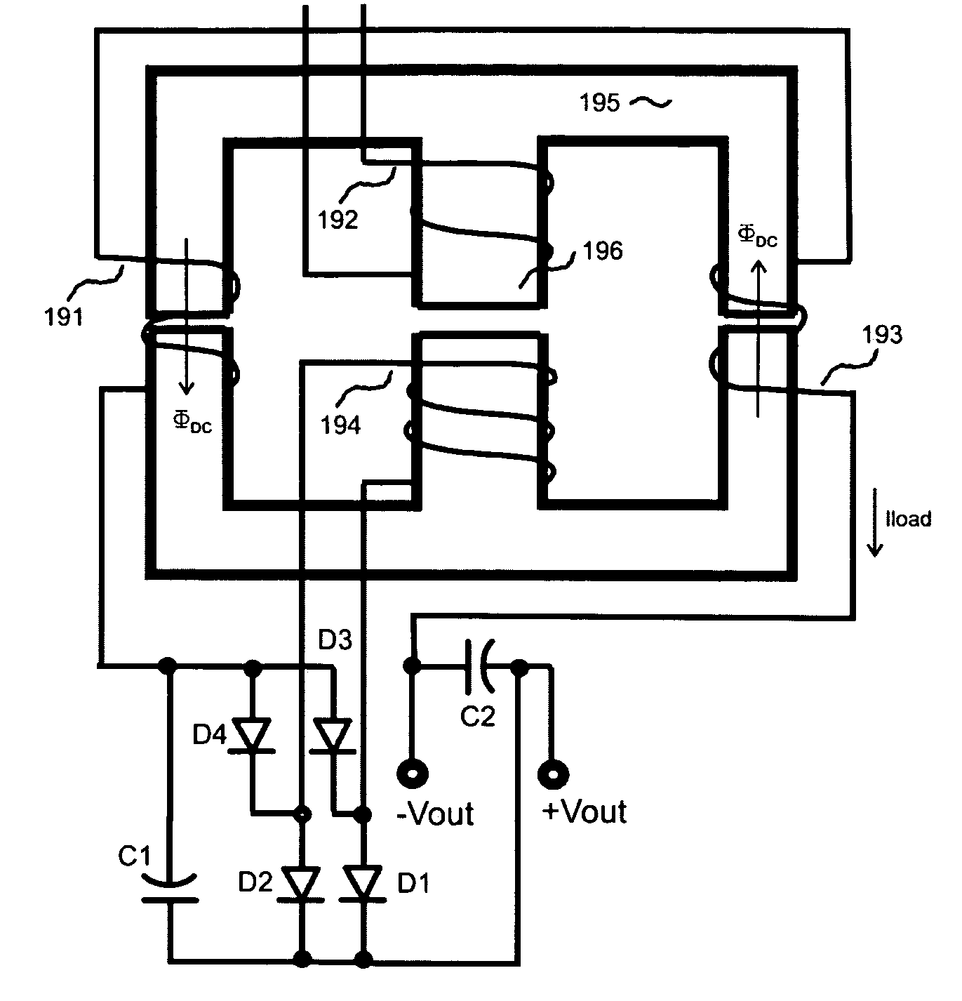
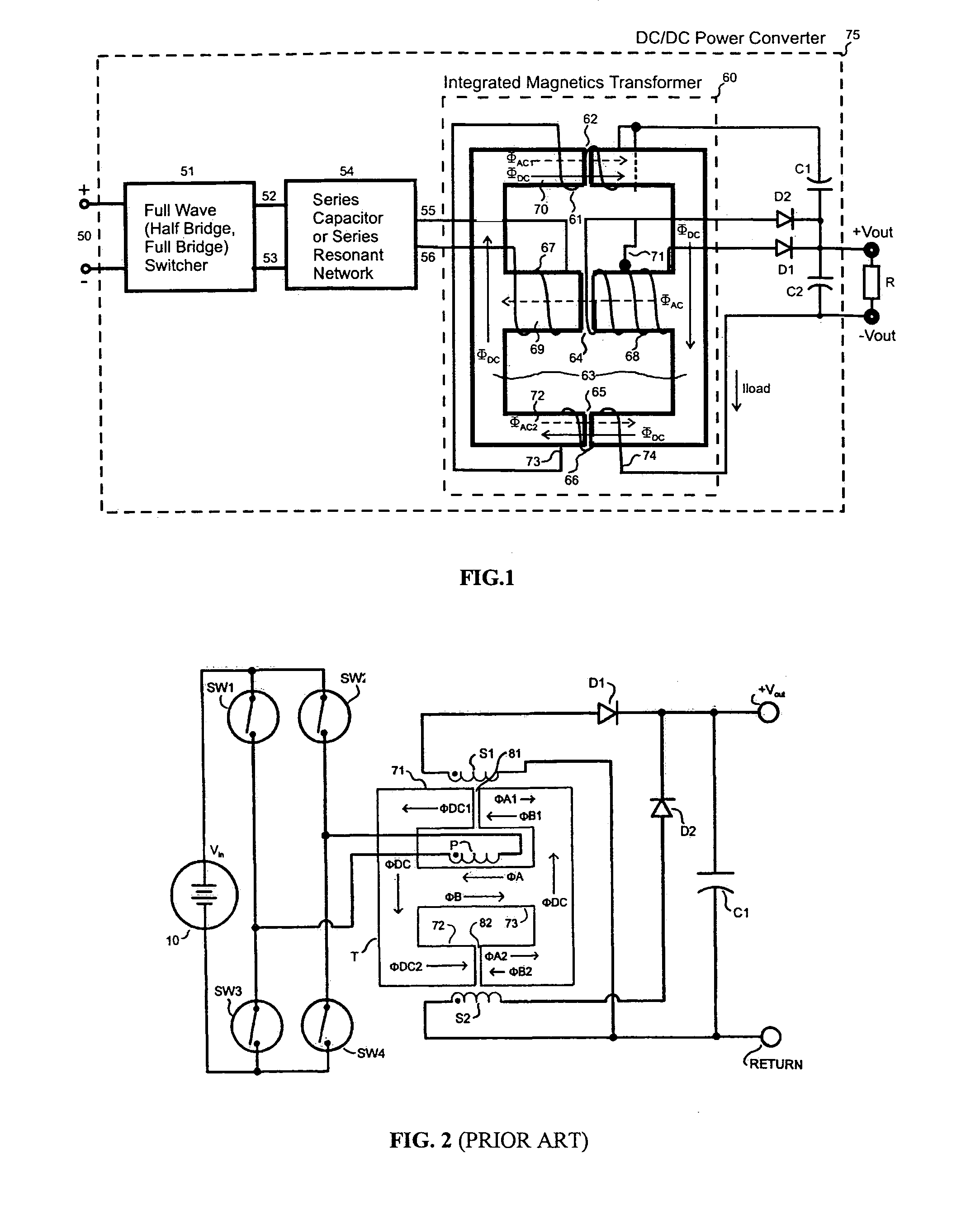
[0029]A schematic of the preferred embodiment of a DC to DC converter embodying the principles of the invention is shown in FIG. 1. A full wave switcher 51, containing controlled switching elements arranged in either half bridge or full bridge configuration is connected to a low impedance dc-source 50. The switching elements in the switcher are consequently turned on and off with 50% duty cycle and their switching frequency is controlled, so that switcher 51 produces square-wave voltage with 50% duty cycle and controlled frequency on its terminals 52 and 53. This square-wave voltage is then applied in series with a capacitor or series resonant network 54 and the resulting voltage between terminals 55 and 56 is then applied to primary winding 67 of an integrated magnetics transformer 60 arranged on an E-shape magnetic core 63. The number of turns of primary 67 is selected so that the ac (alternating current) magnetic flux ΦAC generated by the primary winding 67 provides an optimum bo...


PUM

PropertyMeasurementUnit
saturation flux densityaaaaaaaaaa
magneticaaaaaaaaaa
reverse magnetic polarityaaaaaaaaaa

Abstract

A full wave DC / DC converter magnetically integrates into the transformer assembly the functions of the resonant inductor, magnetizing inductor and the output filter inductor. The primary and the secondary windings are assembled on a gapped center leg of an E-core, while two output filter windings with an equal number of turns are assembled on gapped left and gapped opposed side legs of the E-core. The length of the gaps in the side legs is selected so that the DC current does not saturate the side legs. The two filter windings are connected in series and are oppositely polarized so that the voltages induced in these windings by the primary winding flux cancel each other.

Description

FIELD OF THE INVENTION[0001]The invention relates to series resonant type power converters which employ transformers with integrated resonant, magnetizing and output filter inductors.BACKGROUND ART[0002]It is required from the contemporary DC to DC switch mode power converters to have high power density, high efficiency and low cost. Certain series resonant type DC to DC power converters, such as the conventional series resonant converter, the LLC converter or the resonance tapped transformer converter described in U.S. Pat. No. 5,907,236 attempt to meet these requirements by providing zero voltage switching operation of power transistors on the primary side of the converter and zero current switching operation of output rectifiers on the secondary side.[0003]Zero voltage and zero current switching are well established switching techniques for reducing switching losses. This allows higher switching frequencies, reduced size of magnetic components, increased power density and reduced...

Claims


Application Information

Patent Timeline
Patent Type & Authority Patents(United States)
IPC IPC(8): H02M7/06H01F3/14H01F27/38H01F38/08H02M3/335H02M3/337
CPCH01F27/38H02M3/3376H01F3/14H01F38/08H01F2038/026H02M2001/0048Y02B70/1433Y02B70/1491Y02B70/10H02M1/0048
Inventor PETKOV, ROUMEN D.ANGUELOV, GUEORGUI J.
Owner PETKOV ROUMEN D
Why Eureka
Try Eureka