

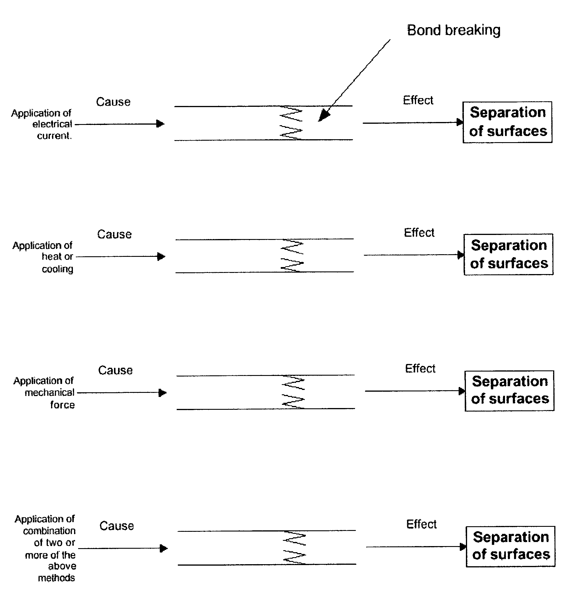
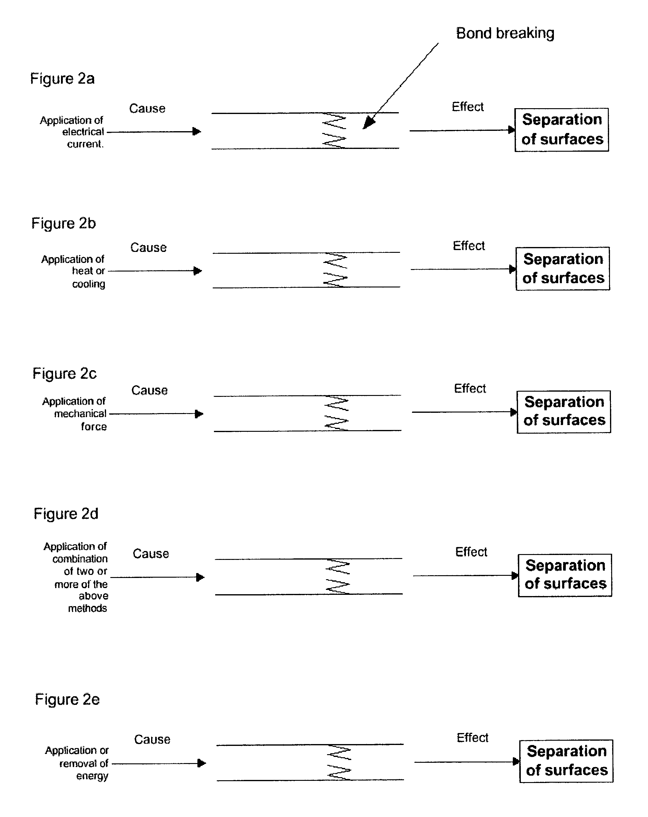
Electrode sandwich separation
a technology of electrodes and sandwich pieces, applied in the manufacture of electrode systems, electric discharge tubes/lamps, tubes with electrostatic control, etc., can solve the problems of affecting the quality of surface matching, etc., and achieve the effect of easy separation
- Summary
- Abstract
- Description
- Claims
- Application Information
AI Technical Summary
Benefits of technology
Problems solved by technology
Method used
Image

Examples
example
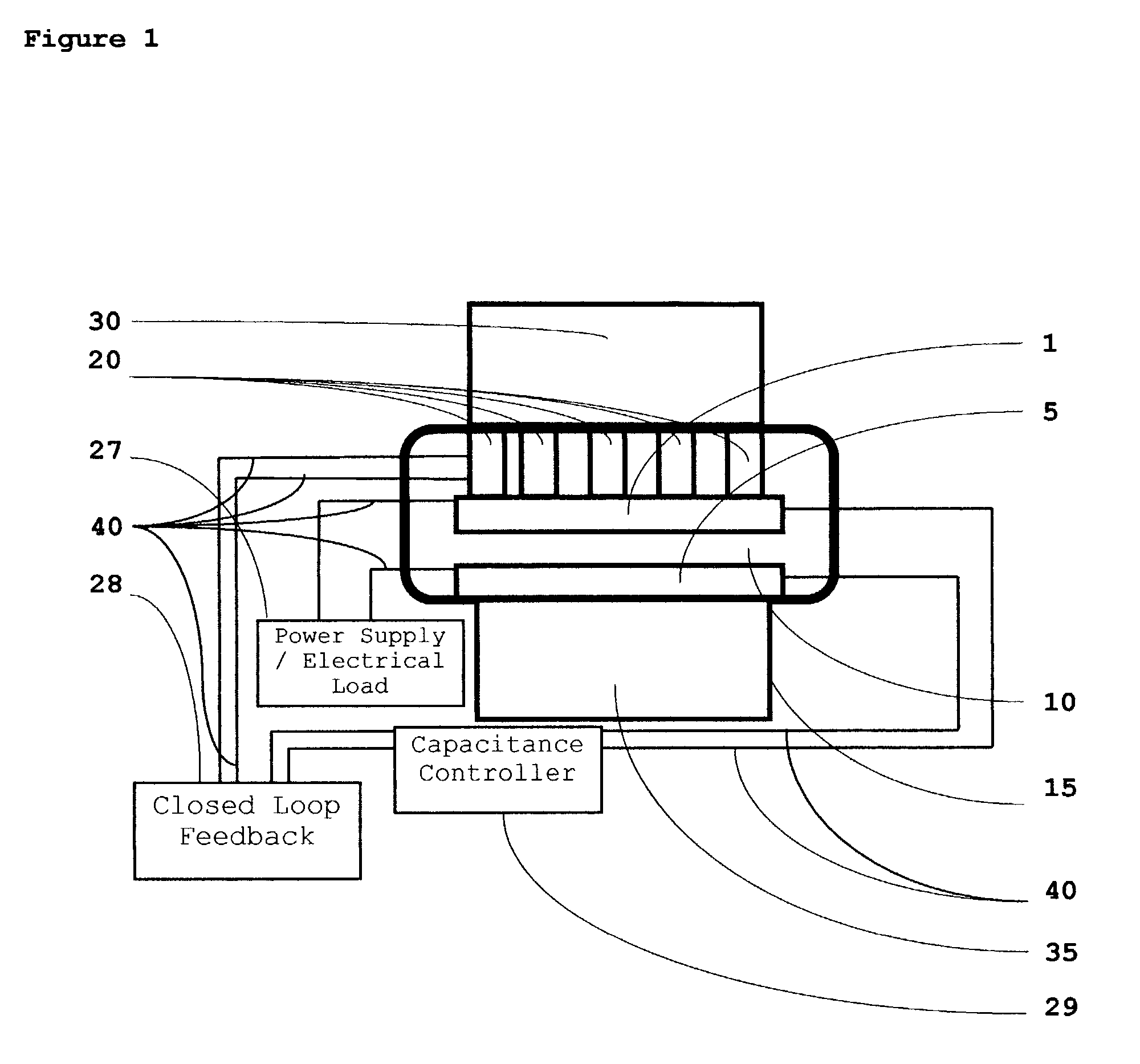
[0050]Referring to FIG. 4a which shows a composite intermediate 410, a doped silicon wafer is used as the substrate. The dopant is n type, and the conductivity of the doped silicon is on the order of 0.05 Ohm cm. A 0.1 μm thick titanium film is deposited over the silicon substrate using DC magnetron sputtering method. A round metallic mask with a diameter of 28 mm is used for the titanium film deposition. After deposition, the titanium is backed with silicon to achieve maximum adhesion of the titanium film to the silicon substrate. Next is the in situ deposition of 1 μm thick silver film using the same method. Deposition regimes for silver are chosen to achieve optimum adhesion of silver to the titanium film. (The optimum adhesion is much less than the adhesion usually used in microelectronics processes.) A layer of copper 500 μm thick is grown electrochemically on the silver film. The copper is grown using ordinary electrochemical growth.
[0051]Next, the sandwich on the border of ti...
PUM
| Property | Measurement | Unit |
|---|---|---|
| temperature | aaaaa | aaaaa |
| temperature | aaaaa | aaaaa |
| thick | aaaaa | aaaaa |
Abstract
Description
Claims
Application Information