Display drive control device and electric device including display device

a control device and drive technology, applied in static indicating devices, cathode-ray tube indicators, instruments, etc., can solve the problems of increasing system costs, increasing power consumption and processing time, and prolonging the time from the start of processing till the actual presentation, so as to achieve high processing speed, increase processing contents, and high functionality

Inactive Publication Date: 2006-11-28
SYNAPTICS JAPAN GK
View PDF8 Cites 47 Cited by
  • Summary
  • Abstract
  • Description
  • Claims
  • Application Information

AI Technical Summary

Benefits of technology

[0005]The trend for color display or large display in the liquid crystal panel accompanies increase of image data, and the introduction of animated displays involves increase of the contents of processing that a microprocessor is demanded to carry out. Accordingly, when the data processing for a transparent display is carried out through the software of a microprocessor, the microprocessor is required to have high functionality and high-speed processing capability, which invites increase of the system cost as well as prolongs the time from starting the processing till actually presenting the transparent display.
[0010]The present invention has been made in view of the above problems, and an object of the invention is to provide a display drive control device capable of lightening the burden on a microprocessor, in a system including a color liquid crystal panel, a liquid crystal display drive control device to drive and control the liquid crystal panel, and a microprocessor. Another object of the invention is to provide a display drive control device capable of reducing the power consumption, in a system including a color liquid crystal panel, a liquid crystal display drive control device to drive and control the liquid crystal panel, and a microprocessor.
[0011]Another object of the invention is to provide a display drive control device capable of efficiently managing the built-in memory to reduce not only the chip size but also the chip cost, in a system including a color liquid crystal panel and a liquid crystal display drive control device to drive and control the liquid crystal panel.
[0016]According to the aforementioned means, a transparent display is implemented, even if a microprocessor does not execute processing with software. Since the built-in memory is followed by the image data processor capable of generating data for the transparent display, when a user desires to repeatedly present the transparent display and non-transparent display, the microprocessor does not need to send the display data to the liquid crystal controller driver LSI, each time the display is switched, which makes it possible to reduce the power consumption as the whole system.
[0017]The image data processor preferably includes a set of bit shifters that bit-shift the image data, and an adder that adds the first image data and the second image data each bit-shifted by the bit shifters. According to the above means, a comparably simple circuit as the bit shifters is able to attain such image data as the transparency 50%, 25%, 12.5%, . . . required for a transparent display. Since the image data processor can be configured with the bit shifters and the adder to save a complicated arithmetic circuit, the display drive control device, while avoiding the cost increase and lightening the burden on the microprocessor, realizes a transparent display.
[0019]Further, in the liquid crystal display drive control device to generate and output drive signals to more than two liquid crystal panels, the display drive control device controls to drive one liquid crystal panel to display and the other panels not to display, sets the storage capacity of a built-in memory to a size in which the sizes of the image data corresponding to each panels are totalized, and makes the built-in memory store the other image data to be overlapped for a transparent display in the storage area corresponding to the non-display panels. Thereby, it is possible to make the built-in memory of a comparably small storage capacity hold the image data for the transparent display.

Problems solved by technology

Accordingly, when the data processing for a transparent display is carried out through the software of a microprocessor, the microprocessor is required to have high functionality and high-speed processing capability, which invites increase of the system cost as well as prolongs the time from starting the processing till actually presenting the transparent display.
The processing for a transparent display by the software will inevitably involve reading out the original image data stored in an external memory, processing the data, and sending the data to a liquid crystal controller driver LSI; accordingly, a repeated execution of a transparent display and a non-transparent display will require the microprocessor to read out the image data from the external memory and send the display data to the liquid crystal controller driver LSI, each time the display is switched, which will unavoidably increase the power consumption and processing time.
However, to enlarge the capacity of the built-in memory will lead to not only increasing the chip size, but also raising the chip cost, which requires an efficient memory management technique for realizing a desired display with a comparably less memory capacity.

Method used


Image

  • Display drive control device and electric device including display device
  • Display drive control device and electric device including display device
  • Display drive control device and electric device including display device

Examples


Embodiment Construction

[0040]The preferred embodiments of the invention will be described with reference to the accompanying drawings.

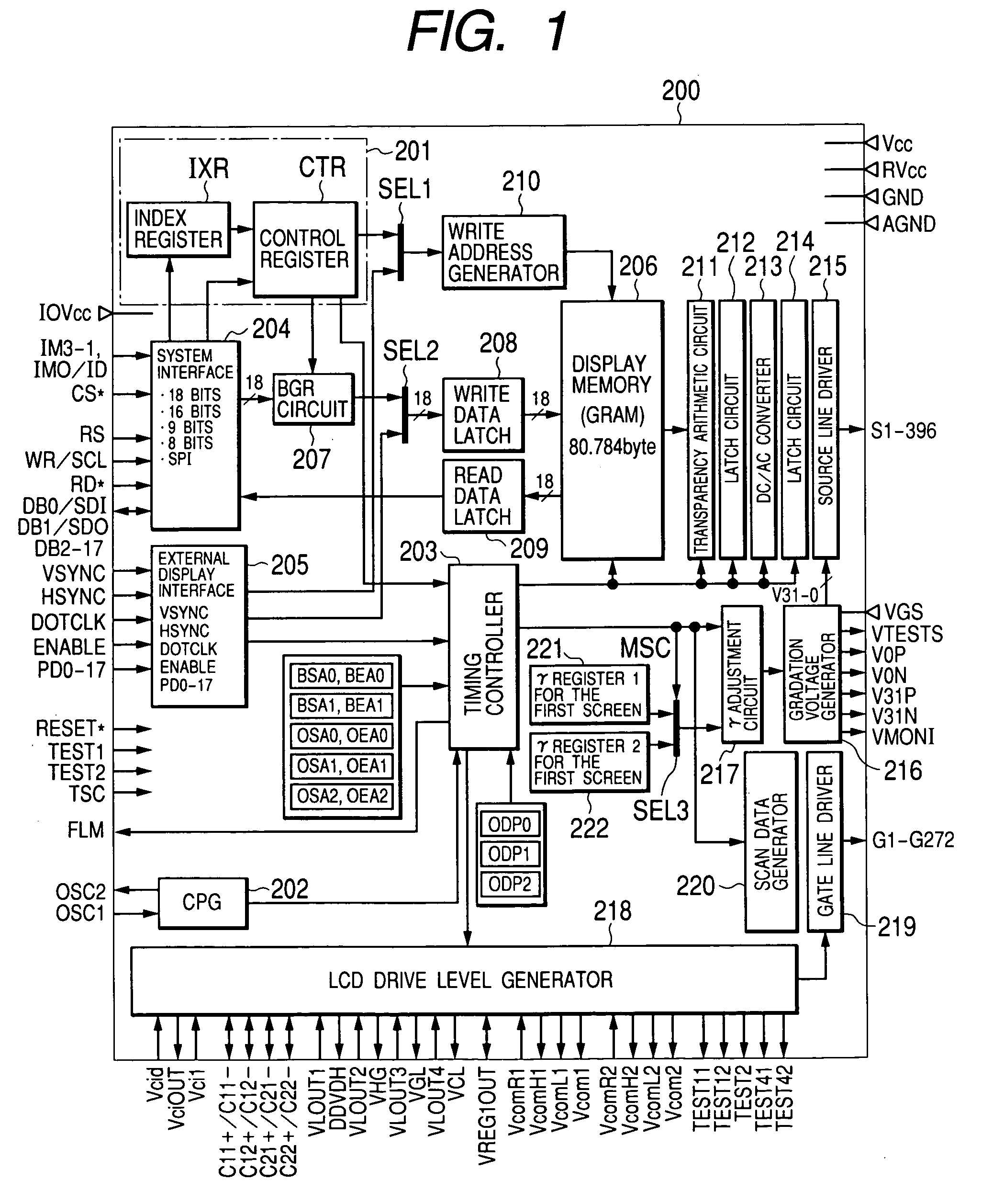
[0041]FIG. 1 illustrates a circuit configuration of a liquid crystal display drive control device (liquid crystal controller driver) relating to the first embodiment of the invention. The liquid crystal controller driver of this embodiment is formed on one semiconductor chip in a semiconductor integrated circuit, which is not restricted to this.

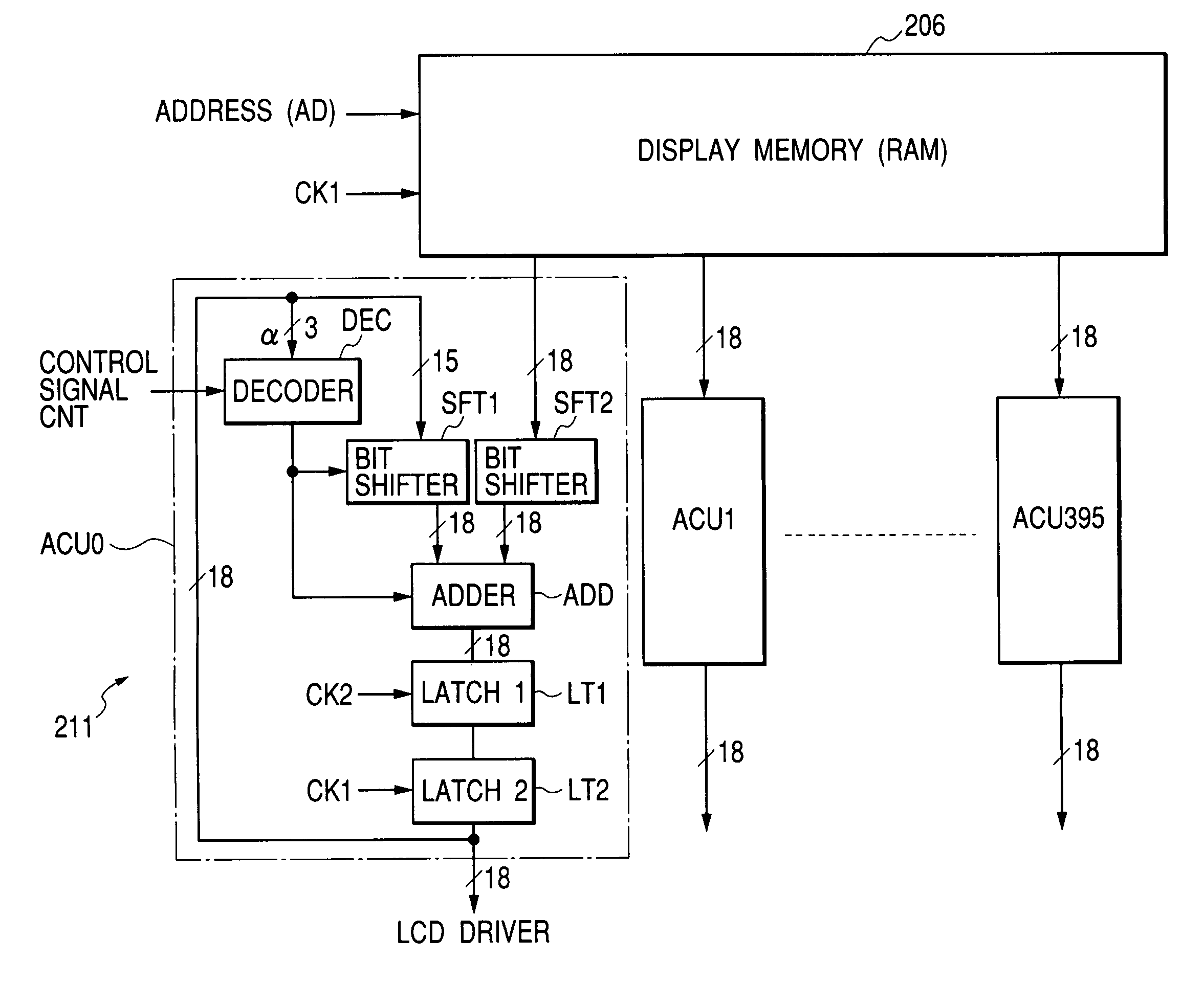
[0042]The liquid crystal controller driver 200 of this embodiment includes a control unit 201 that controls the whole inside of the chip on the basis of the commands from an external microprocessor or a microcomputer or the like, a pulse generator 202 that generates a reference clock pulse to the inside of the chip on the basis of an external oscillation signal or an oscillation signal from an oscillator connected to an external terminal, a timing controller 203 that generates timing signals to supply operational timings to various c...


PUM

PropertyMeasurementUnit
transparentaaaaaaaaaa
transparencyaaaaaaaaaa

Abstract

In a system including a color liquid crystal panel, a drive control device for driving the panel, and a microprocessor, the drive control device reduces the burden on the microprocessor as well as power consumption. In a liquid crystal display drive control device that incorporates a memory for storing image data displayed on a color liquid crystal panel, reads out the image data sequentially from the memory, generates image signals of the three primary colors for each pixel of the panel, and outputs the image signals from external output terminals, the drive control device includes a transparency arithmetic circuit that applies calculation processing to two image data read out from built-in memory and generates data for a transparent display, supplies display data generated by the transparency arithmetic circuit to a driver, and makes the driver generate and output drive signals to the liquid crystal panel.

Description

BACKGROUND OF THE INVENTION[0001]The present invention relates to a technique effective in application to a display drive control device to drive a display device as well as a display drive control device incorporated into a semiconductor integrated circuit, specifically to a technique effective in use for a liquid crystal display drive control device to drive a color liquid crystal panel used in a portable electronic device such as a mobile telephone, and an electronic device such as a mobile telephone using the same.[0002]There has been developing a trend of using a dot-matrix liquid crystal panel having multiple pixels arrayed in matrix two-dimensionally in the display of a portable electronic device such as a mobile telephone or a PDA (Personal Digital Assistant), and in the electronic device is loaded with a liquid crystal display control device (liquid crystal controller) incorporated into a semiconductor integrated circuit that controls the display of the liquid crystal panel...

Claims


Application Information

Patent Timeline
Patent Type & Authority Patents(United States)
IPC IPC(8): G09G5/02G09G5/36G09G5/37G02F1/133G09G3/20G09G3/36
CPCG09G3/3611G09G3/3688G09G5/397G09G5/36G09G5/39G09G2300/0426G09G2310/0278G09G2320/0673G09G2330/021G09G2340/0414G09G2340/0421G09G2340/12G09G2360/04G09G3/36
Inventor SAKAMAKI, GOROUCHIDA, TAKATOSHITANABE, KEIKUROKAWA, YASUHITO
Owner SYNAPTICS JAPAN GK
Why Eureka
Try Eureka