Image display system

a display system and image technology, applied in the field of image display systems, can solve the problems of troublesome reading for each cross-section and troublesome for the reader, and achieve the effect of simplifying the reading of images

Inactive Publication Date: 2006-11-28
FUJIFILM CORP +1
View PDF7 Cites 10 Cited by
  • Summary
  • Abstract
  • Description
  • Claims
  • Application Information

AI Technical Summary

Benefits of technology

[0022]With the image display system of the present invention, the reader need not change the direction of his or her eyes from one image to the other on one screen, reading of images can be simplified.

Problems solved by technology

However, in the case where a number of cross-sections of the object part are displayed in sequence, displaying two images processed under different conditions in a screen for each cross-section makes reading troublesome.
That is, when reading the images, the reader must change the direction of his or her eyes from one image to the other on one screen each time the images of a different cross-section are displayed (generally requiring movement of his or her neck), which is very troublesome for the reader.

Method used


Image

  • Image display system
  • Image display system
  • Image display system

Examples


first embodiment

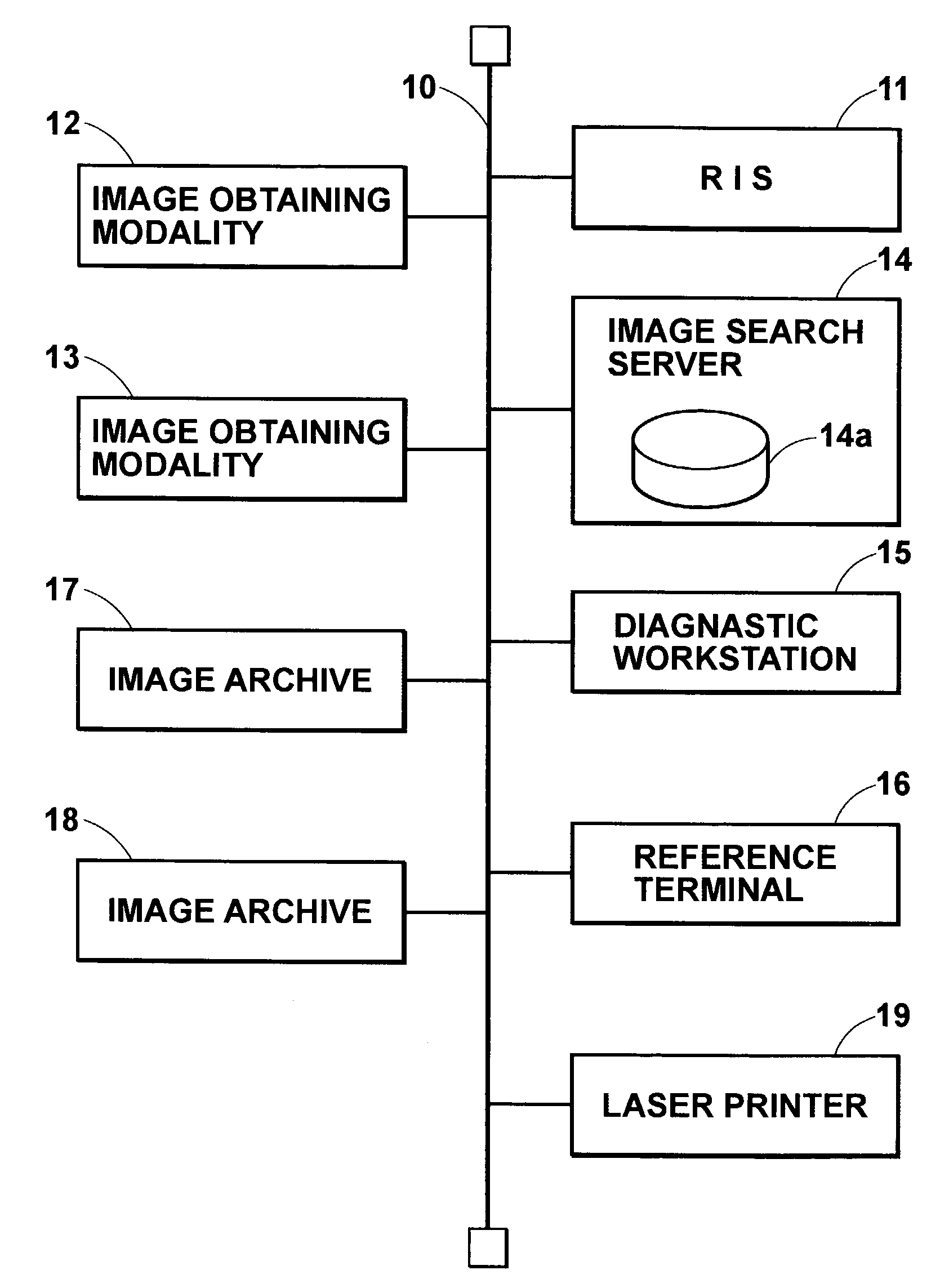
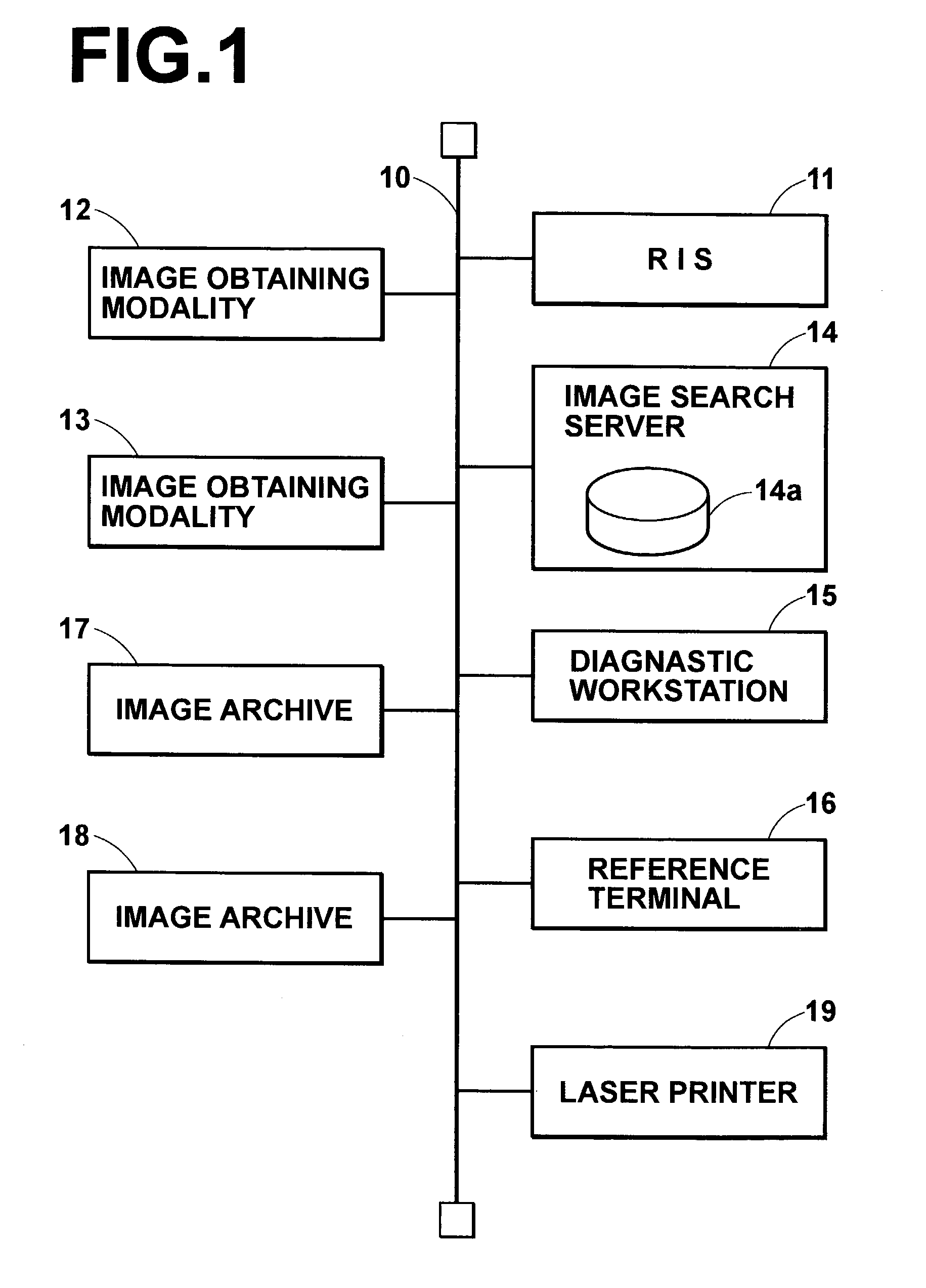
[0034]FIG. 1 is a block diagram showing a medical network system provided with an image display system in accordance with the present invention. This system comprises a network 10 which may be a local area network (LAN) such as an Ethernet®, an FDDI or the like. The LAN may be connected to the internet or the like by way of a leased line or a public network such as an ISDN.

[0035]A radiology information system (RIS) 11, image obtaining modalities 12 and 13, an image search server 14, a diagnostic workstation (a terminal) 15, a reference terminal 16, image archives 17 and 18, and a laser printer 19 connected to the network 10.

[0036]The image obtaining modality 12 or 13 is a system for obtaining an image of an object as digital data such as CT, MRI, CR, RI or US. For example, the image obtaining modality 12 or 13 may obtain the digital data by digitizing an analog image signal obtained by taking an image of the object or by digitally reading an image recorded on a photographic film or ...

second embodiment

[0055]An image display system in accordance with the present invention will be described, hereinbelow, with reference FIG. 6. In FIG. 6, the elements analogous to those shown in FIGS. 3 to 5 are given the same reference numerals and will not be described here unless necessary.

[0056]The image display system of this embodiment differs from that of the first embodiment in that the central processing unit 20 causes the image display unit to display the gradation-processed images 31 and 32 in a different way. That is, in this embodiment, a dynamic-range compressed image 30 of a cross-section in a first slice position (e.g., an uppermost slice position) is first displayed at one of the frames of the screen as shown in FIG. 6 and as a scroll bar 41 on the frame is moved downward by the mouse or the like of the manual operating unit 23, dynamic-range compressed images 30 of cross-sections in second, third, fourth . . . slice positions are displayed at the frame in sequence.

[0057]In this emb...


PUM


Abstract

A dynamic range compression processing and a plurality of other predetermined image processings are separately carried out on an original image data. A dynamic-range-compressed image is displayed on the basis of image data obtained by carrying out the dynamic range compression processing on the original image data and a plurality of otherwise-processed images are displayed on the basis of a plurality of pieces of image data obtained by carrying out the other predetermined image processings on the original image data. An otherwise-processed image is displayed on the basis of image data which is obtained by carrying out the other predetermined image processing on the same original image data as the original image data of the dynamic-range-compressed image which is displayed upon switching action by the operating means.

Description

BACKGROUND OF THE INVENTION[0001]1. Field of the Invention[0002]This invention relates to an image display system, and more particularly to a system for displaying an image subjected to, for instance, dynamic range compression processing.[0003]2. Description of the Related Art[0004]There have been put into practice a CT (Computed Tomography) apparatus or an MRI (Magnetic Resonance Imaging) apparatus for showing in a slice a predetermined part of an object such as a human body. Generally a plurality of cross-sectional images of an object taken at different depths (in the direction perpendicular to the plane of the image) are obtained by the use of such an apparatus in order to know the three-dimensional conditions of the part.[0005]The cross-sectional images are generally recorded as hard copies or displayed by, for instance, a CRT display after subjected to gradation processing so that they are adapted for reading.[0006]In a medical image displayed by, for instance, a CRT, a plurali...

Claims


Application Information

Patent Timeline
Patent Type & Authority Patents(United States)
IPC IPC(8): G06K9/00H04N5/253H04N7/14G01R33/32A61B5/055A61B6/03G06F3/00G06F3/048G06T1/00G06T5/00G06T5/40G09G5/00G09G5/10G09G5/14H04N1/407
CPCA61B6/563G06T5/009H04N1/407H04N19/124H04N19/136H04N19/17H04N19/98A61B6/03G06T2200/24G06T2207/10072G06T2207/30061
Inventor HARA, SHOJI
Owner FUJIFILM CORP
Why Eureka
Try Eureka