Not all
waves are suitable for surfing.
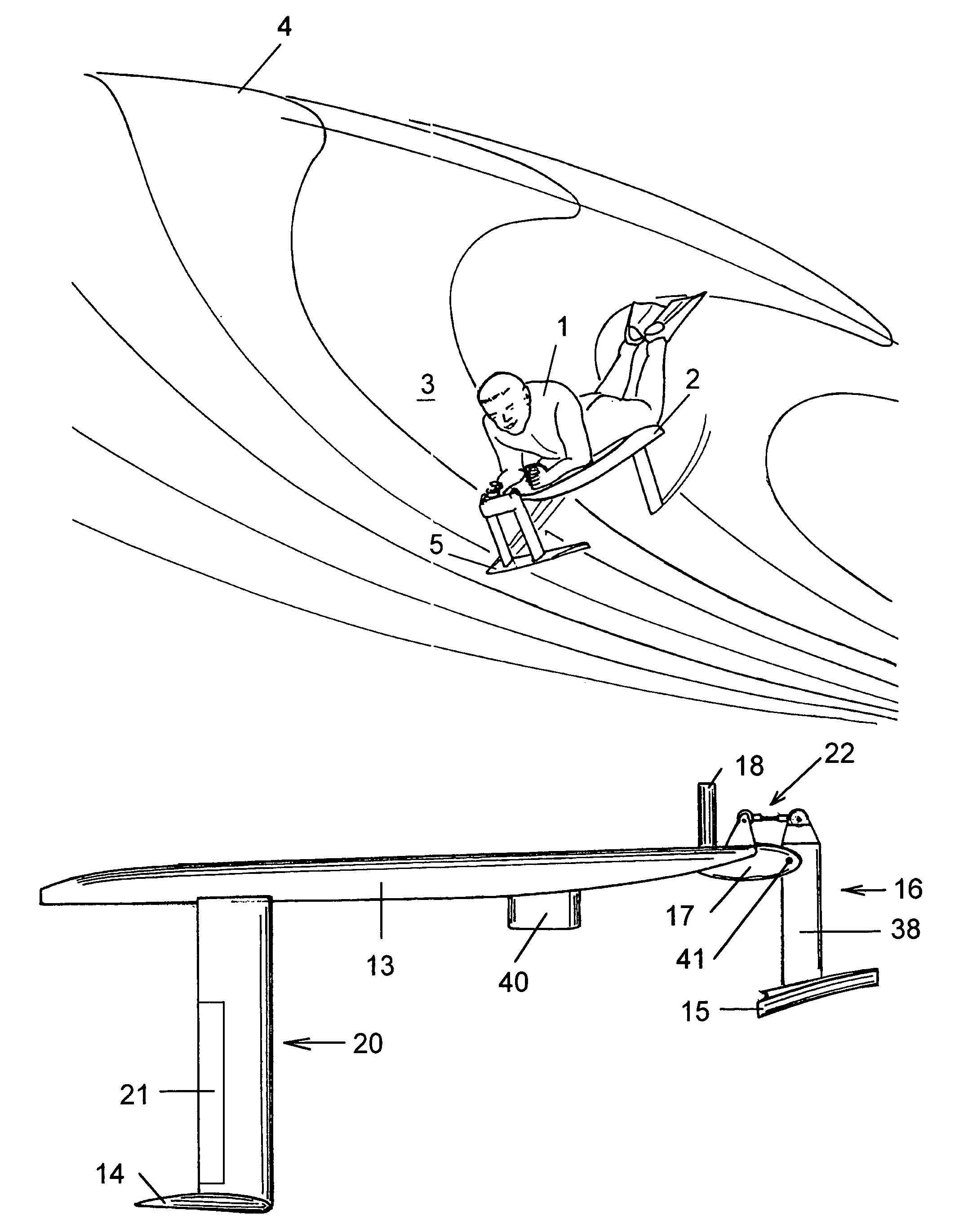
If the wave breaks faster than the surfer can keep up, the rider will not be able to successfully complete the ride.
But motions in the side-to-side direction are considerably restricted by the relatively
short distance between the
heel and the
toe (since all the forces exerted by the surfer on the board must lie within the area bounded by the heels and toes of the surfers two feet, or the surfer will fall).
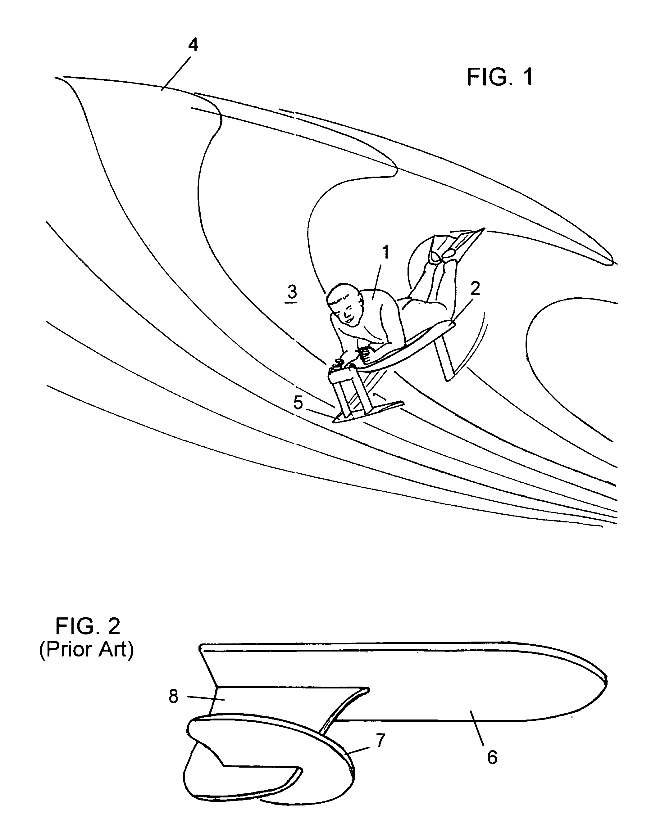
All of these designs have some undesirable design and stability characteristics that may have contributed to the lack of acceptance of this type of craft by the general surfing
community.
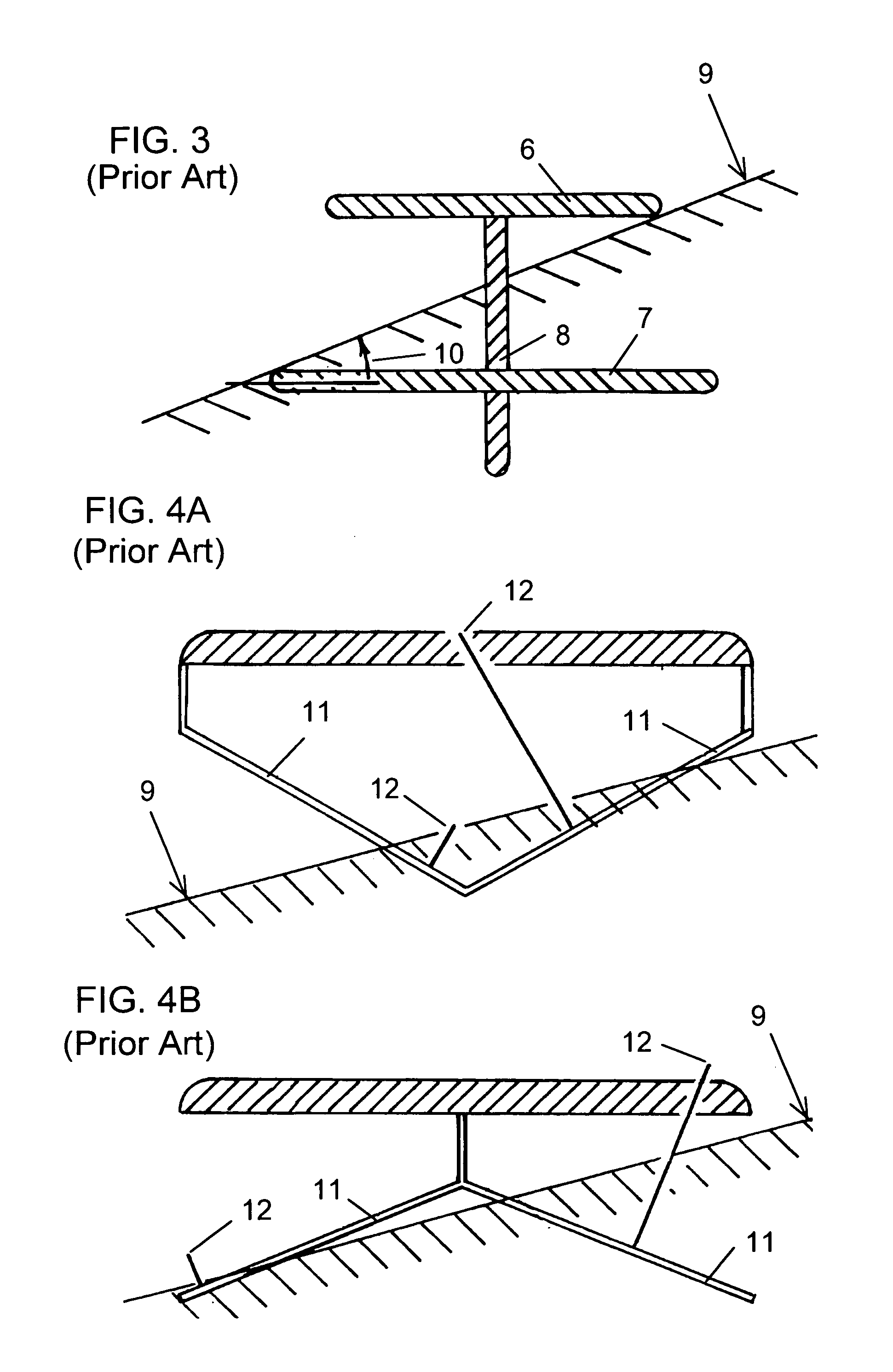
This latter slope, in combination with the design of the board, affects (in a generally adverse manner as the slope increases) the hydrodynamic characteristics of a conventional board with a planing hull.
It also can adversely affect the hydrodynamic efficiency and the control of a foilboard, and presents unique design problems that appear to largely have been ignored in the prior art.
This can increase the induced drag by forcing the foil to be operated at an increased
angle of attack.
Unless the friction and form drag of the foil are reduced by an equal or greater amount due to the reduced
wetted area, the overall drag will increase and the speed potential of the foilboard will be compromised.
idden. The board is inherently unstable in both
pitch and roll (i.e. similar to a unicycle) and hence must be balanced by the rider shifting his weight fore and aft, and from side t
Pitch instability is a deficiency of all the prior art except, perhaps, for the tandem surface-piercing designs disclosed in U.S. Pat. No. 3,747,138 (Morgan, 1973), or if one or more of the foils are broached.
For a hydrofoil board moving through the water at a speed of 20 feet / second, an error of only 1 degree in setting the angle-of-
attack (AOA) of the foil will result in the elevation of the hull above the sea surface changing at a rate of about 0.4 feet per second.
Hence maintaining the hull elevation and avoiding hull contact or the foil
broaching is a virtually impossible task for the rider.
However, even with the large separation between the hull and the foils present in this latter design (which gives the rider more time to make a correction), it is a demanding and distracting task for the rider, and large amplitude variations in hull elevation are evident in a video of the craft in action (Laird, 2002).
All surface-piercing foils of this type introduce new problems if the foil is operated on a sloping sea surface (9).
Hence surface-piercing foils with positive dihedral (e.g. Bateman, 1991) and with negative dihedral (Morgan, 1973) lead to control problems for the rider when the board is operated on a sloping sea surface—and these problems will become even worse if the two foils are spatially separated from each other.
These “unbalanced” conditions also become less manageable as the
dihedral angle of one of the foil segments approaches the transverse
slope angle of the sea surface—especially if the foil area and the speed through the water are such that the
wetted area for equilibrium is about one-half the total foil area.
Another problem with conventional surface piercing foils is that the equilibrium depth varies as the square of the speed of the flow past the foil.
Thus the suitability of a traditional surface-piercing foil as the canard foil for a hydrofoil board is problematic.
The
primary problem with this approach is that ventilation of the upper surface of the foil must be avoided if significant variations in the lift force generated by the foil are to be avoided.
Both of these approaches suffer the same unbalanced lateral force problems as the surface-piercing foil discussed above when operated on an inclined surface.
However, now the force imbalance is increased as there is no opposing second foil segment to partially counterbalance the lateral force generated by the
surface tracking foil.
All of the prior art using fully-submerged foils are unstable in roll and depend on the rider to balance the board by shifting weight from side to side unless the foil is broached.
But surface-piercing foils with negative dihedral are inherently unstable in roll (even more so than are fully-submerged foils).
As noted above, this problem is exacerbated in the presence of a sloping sea surface.
Hence it is unlikely that the rider will be able to balance these craft unless the board is banked such that the hull makes contact with the sea surface.
However, because of the small design transverse
slope angle (˜9 degrees), even a small amount of roll will put the hull in contact with the sea surface.
Hence the craft has a high center of gravity and is quite unstable in roll.

