Liable cardiac muscle diagnosing apparatus and liable cardiac muscle analyzing method by magnetic field measurements

Inactive Publication Date: 2006-12-05
JAPAN SCI & TECH CORP +1
View PDF11 Cites 8 Cited by
  • Summary
  • Abstract
  • Description
  • Claims
  • Application Information

AI Technical Summary

Benefits of technology

[0031]Thus in accordance with the present invention an image representing an intramyocardial current density distribution obtained through a non-invasive magnetic measurement that is superimposed on an anatomical image obtained by processing tomographic, thoracic image data of the same subject undergoing tomography with a separate, medical diagnosis apparatus can be displayed to allow doctors to safely, rapidly and with high precision, and three-dimensionally identify a lesioned part of myocardium presenting an abnormal current density distribution or a physiologically viable part of myocardium.

Problems solved by technology

However, conventional electrocardiography is insufficient for example to determine the location, size and geometry of a lesioned or viable part of myocardium prior to heart surgeries.
As such, it has been significantly difficult to accurately determine an affected part from information obtained from electrocardiography.
However, they can hardly be used to recognize the location, size and geometry of lesioned and viable parts of myocardium.
Accordingly, employing them in a controlled area is obligatory and also expensive.
However, they do not have a precision necessary for diagnosis, i.e., as high a precision as necessary for determining the level of a rejection, Accordingly after he

Method used


Image

  • Liable cardiac muscle diagnosing apparatus and liable cardiac muscle analyzing method by magnetic field measurements
  • Liable cardiac muscle diagnosing apparatus and liable cardiac muscle analyzing method by magnetic field measurements
  • Liable cardiac muscle diagnosing apparatus and liable cardiac muscle analyzing method by magnetic field measurements

Examples


first embodiment

[0054

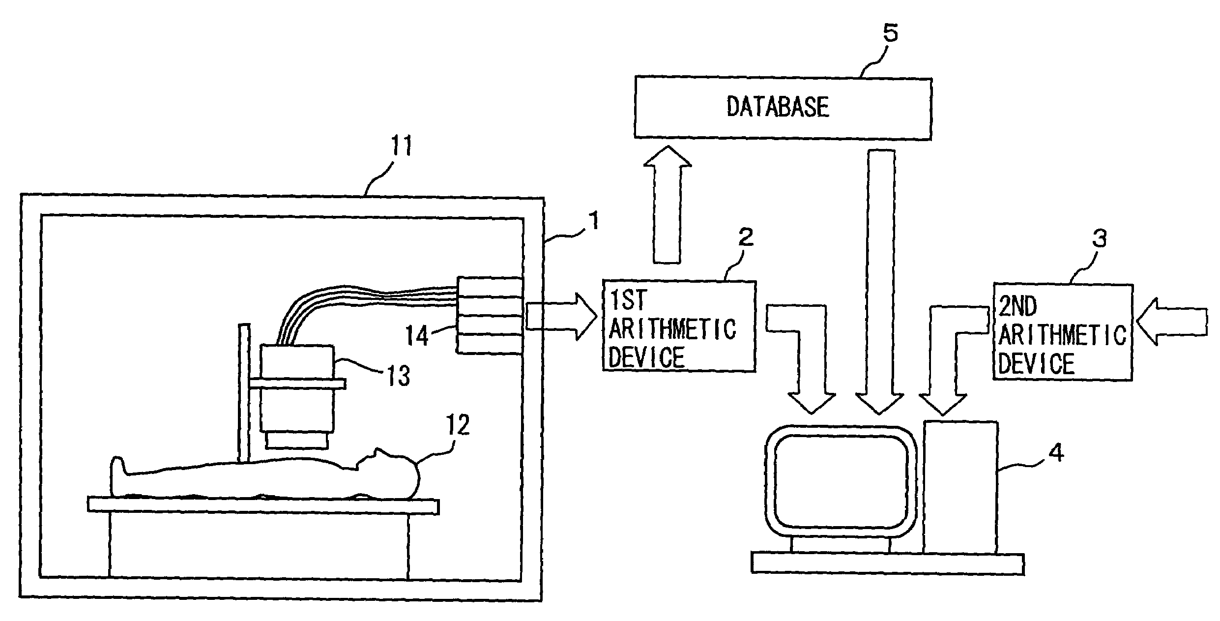
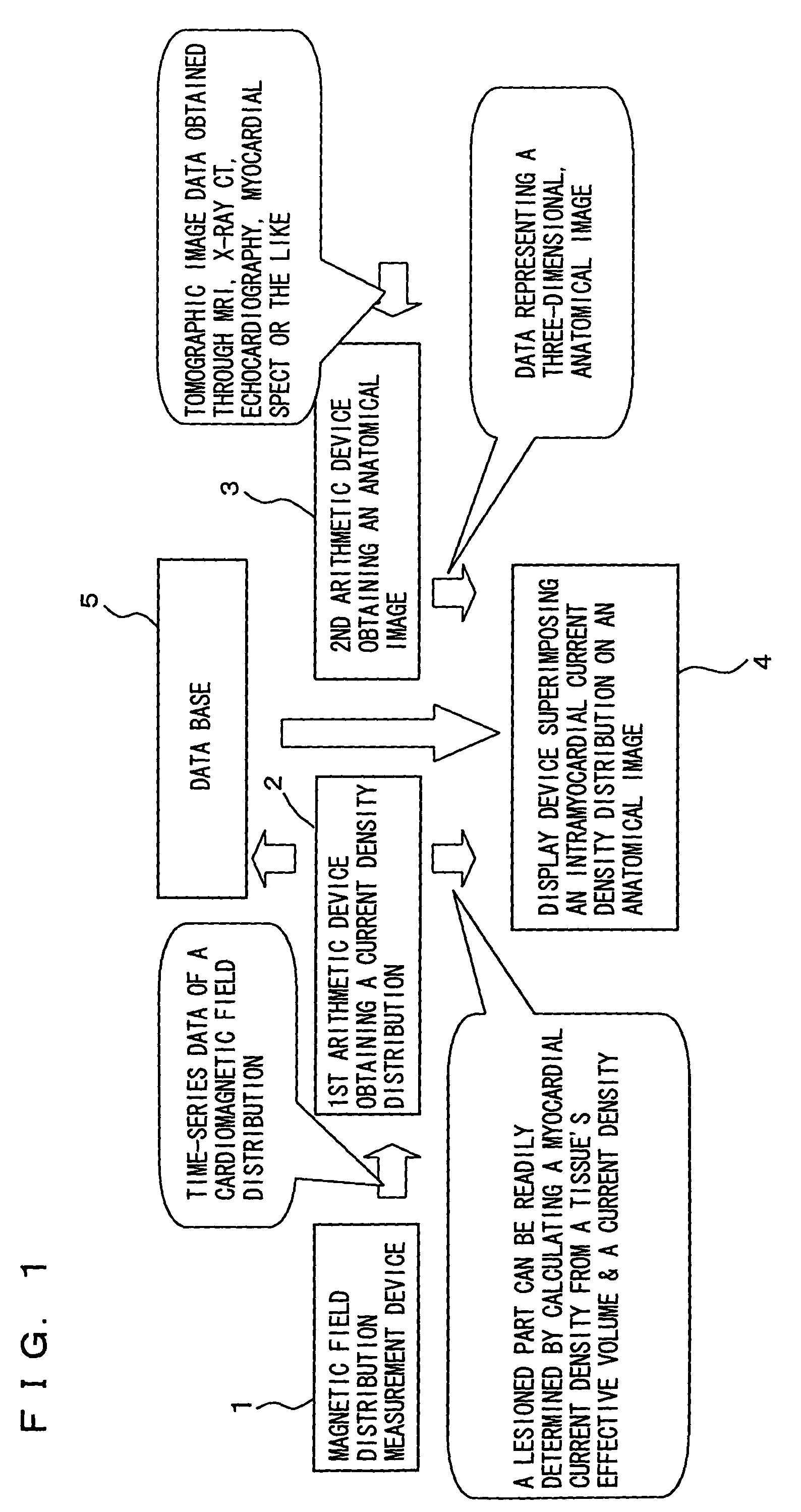
[0055]FIG. 1 is a functional block diagram schematically showing a configuration of an apparatus in accordance the present invention in a first embodiment employing a magnetic measurement to diagnose viable myocardium.

[0056]As shown in FIG. 1, a magnetic field distribution measurement device 1 for example uses a measurement means such as a SQUID magnetometer, as will be described hereinafter more specifically, to provide a non-contact magnetic measurement on a subject's chest at a plurality of coordinates to obtain a plurality of time-series magnetic data corresponding to the plurality of coordinates. The plurality of time-series magnetic data are then used to generate and output time-series magnetic field distribution data of a magnetic field existing on the subject's chest, i.e., of the subject's heart.

[0057]The cardiac, time-series magnetic field distribution data provided by magnetic field distribution measurement device 1 is used by a first arithmetic device 2 for example ...

second embodiment

[0120

[0121]In the first embodiment, forming an anatomical image entails obtaining a large number of tomographic images of a subject and a test employing MRI, x-ray CT or the like is accordingly, previously conducted. This results in an increased number of tests and an increased burden on patients and also an obstacle to a treatment directly linked to a test.

[0122]The present invention in a second embodiment can provide a viable-myocardium diagnosis apparatus and analysis method employing a magnetic measurement capable of eliminating the formation of an anatomical image to conduct a reduced number of tests and carry out a diagnosis and a test such that they are directly linked.

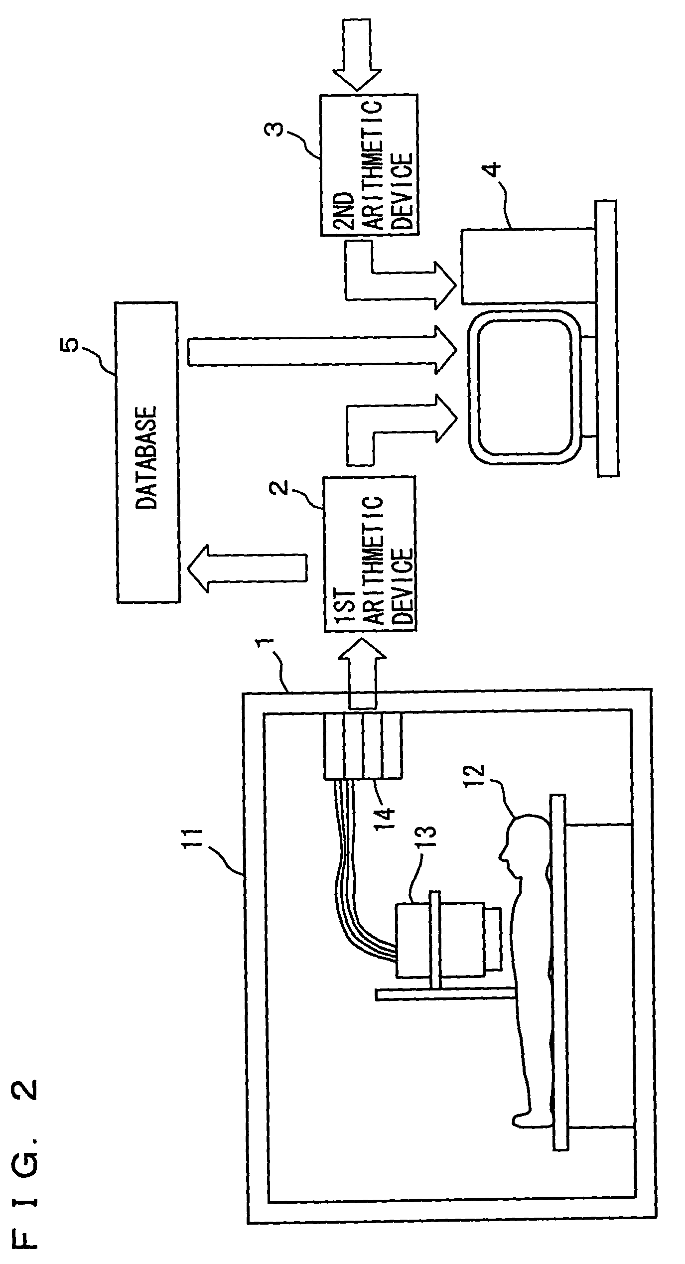
[0123]FIG. 13 is a functional block diagram schematically showing a configuration of the viable-myocardium diagnosis apparatus employing magnetic measurement in the second embodiment.

[0124]With reference to FIG. 13, magnetic field distribution measurement device 1 will not be described as it has been described ...


PUM


Abstract

A magnetic field distribution measurement device (1) provides a non-contact magnetic measurement on a subject's chest at a plurality of coordinates and forms therefrom time-series magnetic field distribution data. A first arithmetic device (2) in response generates image data representing a three-dimensional, intramyocardial current density distribution. A second arithmetic device (3) receives a plurality of tomographic image data separately obtained by a tomographic diagnosis apparatus and processes the data to generate three-dimensional, anatomical image data. A display device (4) receives these data and displays on an anatomical image an image representing an intramyocardial current density. Thus in a ventricle a lesioned or viable part of myocardium can be readily identified in location, size, geometry and level. Furthermore, the anatomical image may be replaced with an image representing a normal stimulation propagation circuit and serving as a template.

Description

[0001]This application is the national phase under 35 U.S.C. § 371 of PCT International Application No. PCT / JP01 / 06193 which has an International filing date of Jul. 17, 2001, which designated the United States of America.[0002]1. Technical Field[0003]The present invention relates generally to viable myocardium diagnosis apparatuses and analysis methods employing a magnetic measurement and particularly to those employing a non-contact magnetic measurement to non-invasively identify a lesioned part of myocardium that might cause an oscillation loop (a reentry circuit) of an abnormal electric current in right and left ventricles or a viable part of myocardium.[0004]2. Background Art[0005]Conventionally, electrocardiograms has been generally adopted as a technique to diagnose heart diseases.[0006]However, conventional electrocardiography is insufficient for example to determine the location, size and geometry of a lesioned or viable part of myocardium prior to heart surgeries.[0007]Thi...

Claims


Application Information

Patent Timeline
IPC IPC(8): A61B5/02A61B5/055G01R33/035A61B5/352A61B6/03G06T1/00
CPCA61B5/04007A61B5/0456A61B5/05A61B6/032A61B6/037A61B6/503A61B6/5235A61B6/5247A61B8/5238G06F19/3437A61B5/055A61B5/413A61B5/743G16H50/50A61B5/243A61B5/352
Inventor NAKAI, KENJIYOSHIZAWA, MASAHITOKAWAZOE, KOHEIYAMAZAKI, KEITAFUJITA, SATOSHITAMURA, ITSURO
Owner JAPAN SCI & TECH CORP
Why Eureka
Try Eureka