
CMP for corrosion-free CoFe elements for magnetic heads

a cofe element, corrosion-free technology, applied in the direction of lapping machines, instruments, other chemical processes, etc., can solve the problems of endangering cofe components, limiting the ability of the pole tip material to conduct very-high densities of magnetic flux, etc., to achieve higher densities of media storage, small tracks, and high yield of undamaged parts

Inactive Publication Date: 2006-12-05
WESTERN DIGITAL TECH INC
View PDF8 Cites 0 Cited by
  • Summary
  • Abstract
  • Description
  • Claims
  • Application Information

AI Technical Summary

Benefits of technology

The present invention provides a method for manufacturing magnetic heads using CoFe elements without corrosion damage to the CoFe material common in prior CMP processes. The method includes using a slurry of Al2O3 and adjusting the concentration of H2O2 in the slurry to within a range of 6-12% by volume and balancing mechanical polishing action. The method also allows for the use of CoFe as a fabrication material for magnetic head elements, reducing the physical dimensions of the poles and increasing the storage capacity of media. The method also produces a faster Material Removal Rate (MRR) than that generally used for NiFe elements, reducing processing time and increasing throughput. The method can also planarize elements of both CoFe and Al2O3 materials in a single CMP processing step by adjusting the recipe of slurry used for CMP. The invention also provides a magnetic head made of CoFe material with no pitting and pinhole corrosion, and a method for manufacturing the same. The technical effects of the invention include improved performance and reliability of magnetic heads.

Problems solved by technology

Although this has worked well in the past, a limit is being approached as far as the ability of the pole tip material to conduct very-high densities of magnetic flux.
However, CoFe is more chemically active than NiFe, and chemicals used in manufacturing processes of these magnetic heads can end up damaging the CoFe components, especially during the Chemical Mechanical Polishing (CMP) stages. FIGS. 5–7 show exemplary heads having elements made of CoFe, which have been damaged by pits produced by chemical action during the CMP process, using standard methods and materials.

Method used


Image

  • CMP for corrosion-free CoFe elements for magnetic heads
  • CMP for corrosion-free CoFe elements for magnetic heads
  • CMP for corrosion-free CoFe elements for magnetic heads

Examples


Embodiment Construction

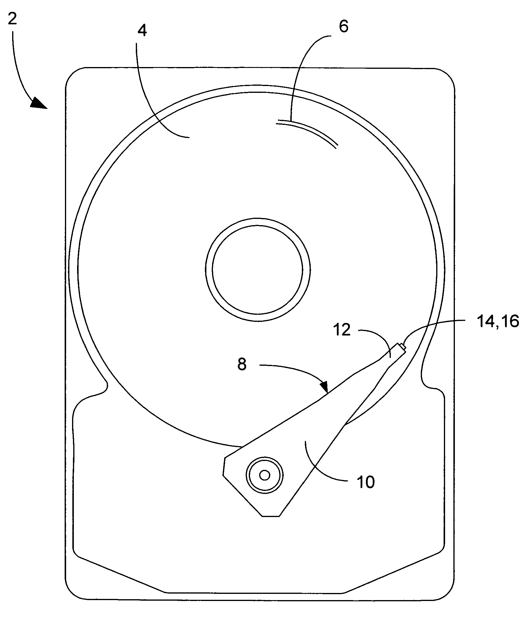
[0030]A magnetic disk drive 2 is shown generally in FIG. 1, having one or more magnetic data storage disks 4, with data tracks 6 which are written and read by a data read / write device 8. The data read / write device 8 includes an actuator arm 10, and a suspension 12 which supports one or more magnetic heads 14 included in one or more sliders 16.

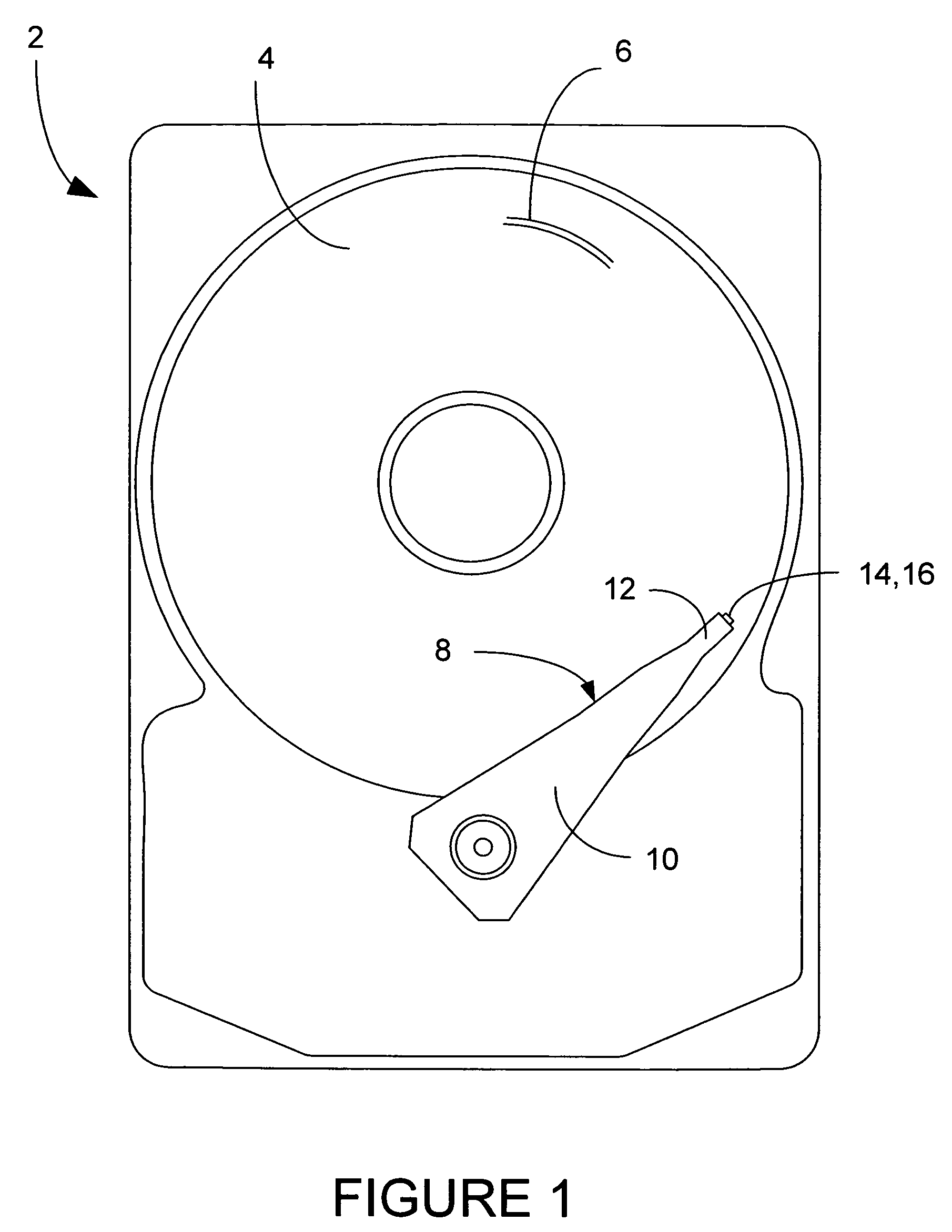
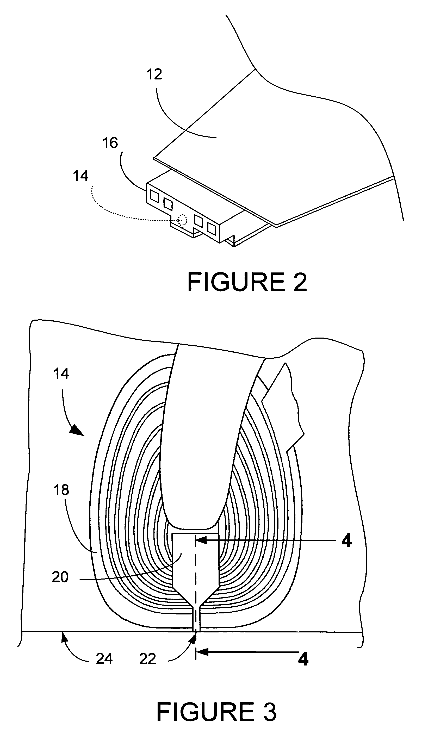
[0031]FIG. 2 shows a slider 16 in more detail being supported by suspension 12. The magnetic head 14 is shown in dashed lines, and in more detail in FIG. 3. The magnetic head 14 includes a coil 18 and poles 20 having tips 22. The magnetic head 14 flies on an air cushion between the surface of the disk 4 and the air bearing surface (ABS) 24 of the slider 16.

[0032]FIG. 4 is a cut-away view of the magnetic head 14 structure as taken from line 4—4 of FIG. 3. The write head portion 26 and the read head portion 28 are generally shown, with the read head sensor 30 and the ABS 24. The write head 26 in the present invention has elements of CoFe material...


PUM

PropertyMeasurementUnit
particle sizeaaaaaaaaaa
pressureaaaaaaaaaa
pressureaaaaaaaaaa

Abstract

A method of manufacture of magnetic heads which include CoFe elements using CMP is presented. The method includes providing a slurry of Al2O3, adjusting the concentration of H2O2 in said slurry to within a range of 6–12% by volume and balancing mechanical polishing action. The balancing is done by adjusting the table speed of a mechanical polisher to within a range of 55–90 rpm, and adjusting polishing pressure to within a range of 5–7 psi. Also a magnetic head having elements made of CoFe material made by this method is disclosed.

Description

BACKGROUND OF THE INVENTION[0001]1. Field of the Invention[0002]The present invention relates generally to magnetic heads and their fabrication, and more specifically to manufacture of pole pieces for write heads which contain elements made of CoFe.[0003]2. Description of the Prior Art[0004]A computer disk drive stores and retrieves data by positioning a magnetic read / write head over a rotating magnetic data storage disk. The head, or heads, which are typically arranged in stacks, read from or write data to concentric data tracks defined on surface of the disks which are also typically arranged in stacks. The heads are included in structures called “sliders” into which the read / write sensors are imbedded during fabrication. The goal in recent years is to increase the amount of data that can be stored on each hard disk. If data tracks can be made narrower, more tracks will fit on a disk surface, and more data can be stored on a given disk. The width of the tracks depends on the width...

Claims


Application Information

Patent Timeline
Patent Type & Authority Patents(United States)
IPC IPC(8): B44C1/22B24B37/04C09K3/14G11B5/31
CPCB24B37/044C09K3/1472G11B5/3163
Inventor BERGEVIN, CHRISTOPHER W.GUTHRIE, HUNG-CHINHARRIS, III, TOM KINGJIANG, MINGYANG, JOHN JAEKOYUN
Owner WESTERN DIGITAL TECH INC
Learn More