Optical protection scheme

a protection scheme and optical technology, applied in the field of optical protection schemes, can solve the problems of increasing complexity and difficulty in managing the communication network, unpractical centralised management, and affecting and achieve the effect of reducing the level of redundancy

Active Publication Date: 2006-12-05
CIENA
View PDF5 Cites 13 Cited by
  • Summary
  • Abstract
  • Description
  • Claims
  • Application Information

AI Technical Summary

Benefits of technology

[0064]Conventional photonic network protection schemes involve providing redundant capacity with the network which is used to reroute traf

Problems solved by technology

In recent years, communications networks have proliferated and become increasingly complex and difficult to manage.
Whilst network management centres are able to implement most functions of network management in a centralised manner, centralised management is not practical whenever fast responses are required, such as responding to failures and setting up and down connections which may need to be done on relatively rapid timescales.
This partitioning of the network management can create problems.
For example, it may no longer be possible for a network operator controlling the network elements and links at the optical network layer to assess how any optical degradation is affecting the quality of service provided in higher layers, for example in the client layer network's electronic domain.
Optical degradation can occur rapidly or slowly, and is particularly likely to occur when the photonic or all optical network layer of a communications network uses Dense Wavelength Division Multiplexing (DWDM), for example, when a new wavelength channel is injected into an optical link carrying an existing wavelength channel.
Channels in a DWDM system are closer in wavelength than in systems using a simpler Wavelength Division Multiplexed transmissi

Method used


Image

  • Optical protection scheme
  • Optical protection scheme
  • Optical protection scheme

Examples


Embodiment Construction

[0077]Any range or device value given herein may be extended or altered without losing the effect sought, as will be apparent to the skilled person for an understanding of the teachings herein. The best mode of the invention as apparent to the inventor will now be described with reference to the accompanying drawings.

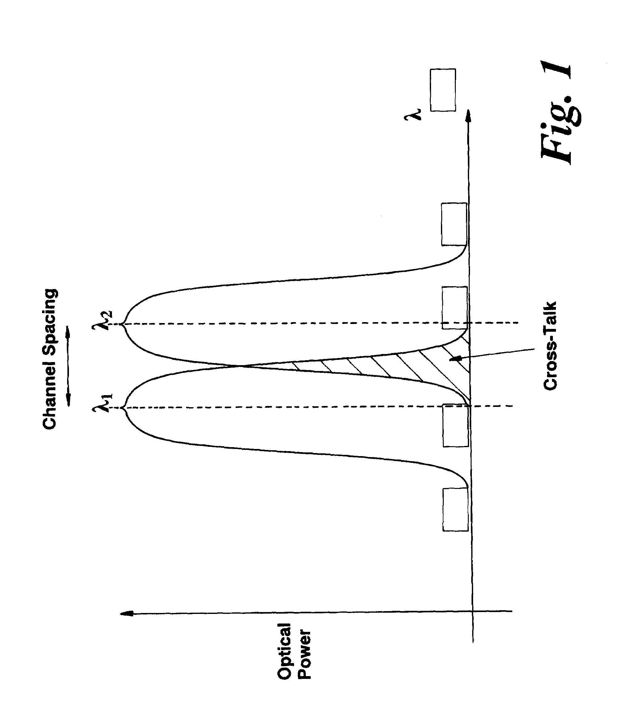
[0078]FIG. 1 of the accompanying drawings shows schematically how channels provided in an optical layer network, where traffic is wavelength division multiplexed, may experience cross-talk if the channel margins become too narrow. In FIG. 1, a first channel λ1, and a second channel λ2 are separated by a narrow wavelength band or channel margin. Irregularities in transmission media, or regenerative processes, filtering etc., may all cause distortion of the channels. Chromatic distortion which broadens the channels can generated significant cross-talk, which leads to transmission errors being detected when the optical signals are converted into electronic signals at node...


PUM


Abstract

A method for triggering an optical protection event in an optical layer of a network comprising the following steps: i) monitoring the optical performance of an optical signal transmitted within the optical layer of the network; ii) provisioning optical protection in the event the monitored optical performance falls below a first threshold level; and iii) triggering an optical protection event, in the event the monitored optical performance falls further to below a second threshold level. The monitoring step is performed within the optical layer of the network by using a proxy to determine an optical performance characteristic which corresponds to the transmission quality of electronic signals extracted from said optical layer signal.

Description

FIELD OF THE INVENTION[0001]The present invention relates to an optical protection scheme, in particular to a method for triggering an optical protection event within the optical layer of a communications network, and to various related aspects.BACKGROUND TO THE INVENTION[0002]In recent years, communications networks have proliferated and become increasingly complex and difficult to manage. Whilst network management centres are able to implement most functions of network management in a centralised manner, centralised management is not practical whenever fast responses are required, such as responding to failures and setting up and down connections which may need to be done on relatively rapid timescales.[0003]For functions which require actions to take place on such relatively rapid timescales, decentralised management can be used, which enables faster response times to failures, and enables large and complex networks to be more easily managed. Different domains of a networks may t...

Claims


Application Information

Patent Timeline
IPC IPC(8): H04B10/00
CPCH04B10/0795H04J14/0227H04J14/0293H04J14/0241H04J14/021H04J14/0283H04J14/0284H04J14/0286H04J14/0291H04J14/0295
Inventor WARBRICK, KEVIN
Owner CIENA
Why Eureka
Try Eureka