Navigation system and navigation method for movable body, program storage device and computer data signal embodied in carrier wave
a navigation system and program storage technology, applied in the direction of navigation instruments, process and machine control, instruments, etc., can solve the problems of driver driver usually receives mental and/or physical stress, and the behavior of a vehicle that is automatically controlled is sometimes different from the driving condition of a driver,
- Summary
- Abstract
- Description
- Claims
- Application Information
AI Technical Summary
Benefits of technology
Problems solved by technology
Method used
Image
Examples
first embodiment
(I) First Embodiment
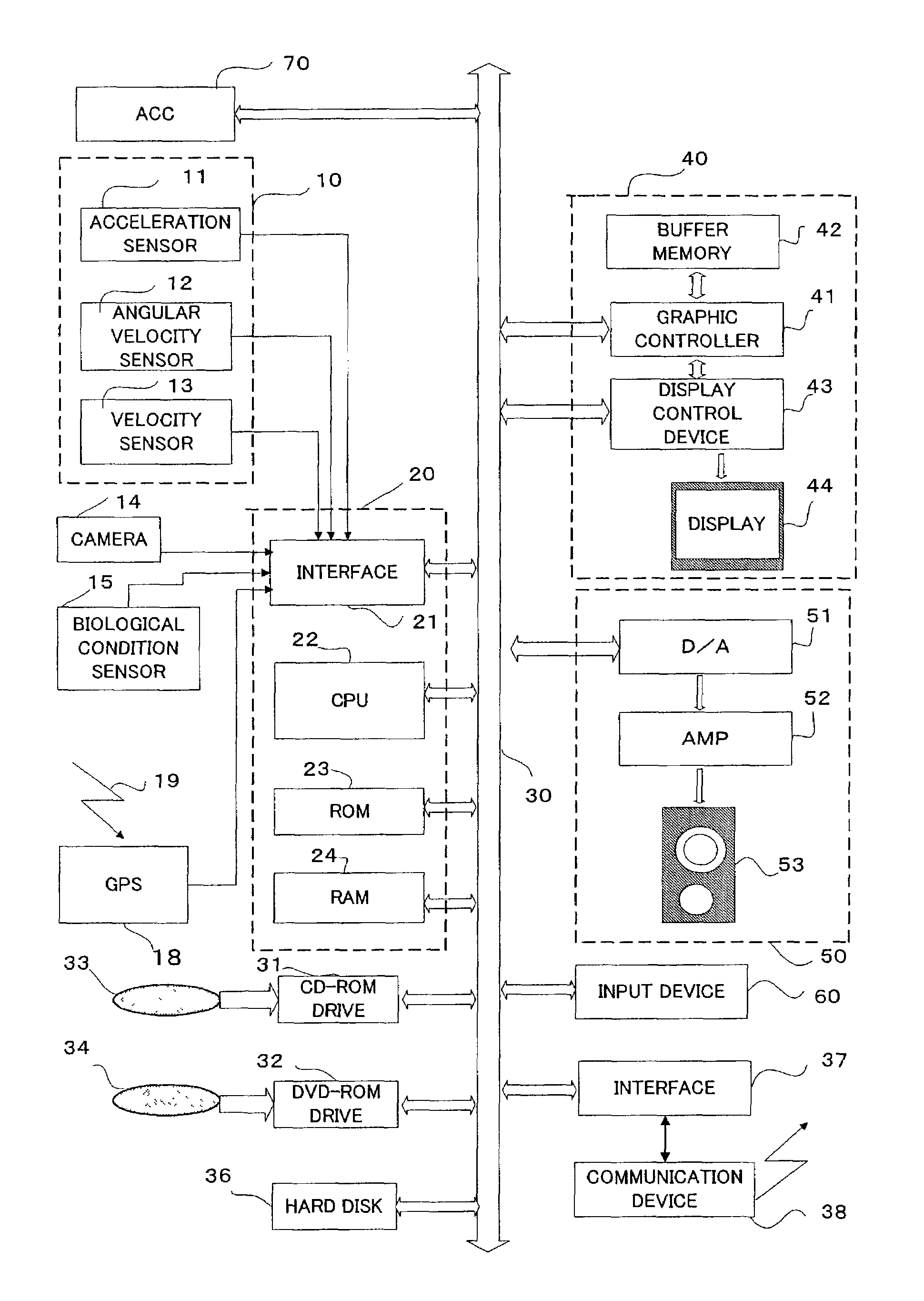
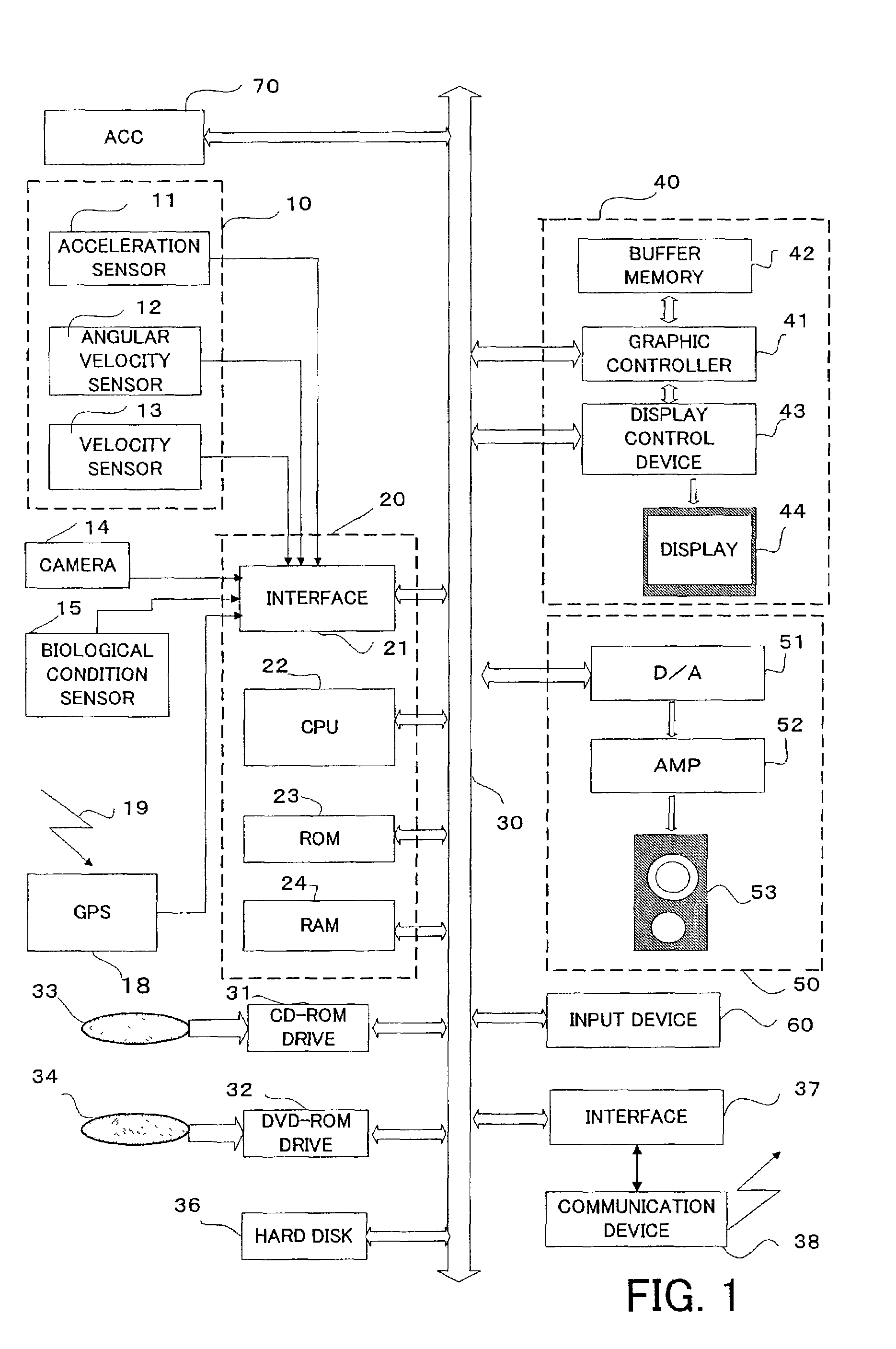
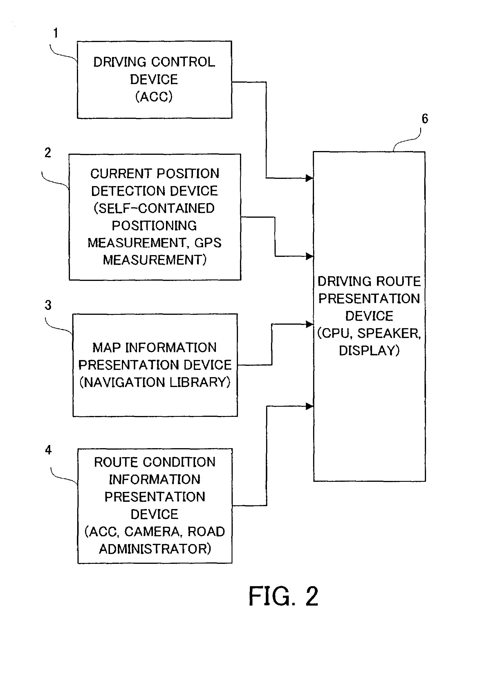
[0072]Firstly, a navigation system for a movable body of the first embodiment will be explained with reference to FIG. 1 to FIG. 5. Incidentally, a “biological condition sensor 15” shown in FIG. 1 is used in the second embodiment, which will be explained later, and is not used in the explanation of the first embodiment.
[0073]As shown in FIG. 1, the navigation system for a movable body in the first embodiment is provided with a self-contained positioning apparatus 10, a camera 14, a GPS receiver 18, a system controller 20, a CD-ROM drive 31, a DVD-ROM drive 32, a hard disk unit 36, an interface 37 for communication, a communication device 38, a display unit 40, an audio output unit 50, an input device 60, and an ACC apparatus 70.
[0074]The self-contained positioning apparatus 10 is constructed to include an acceleration sensor 11, an angular velocity sensor 12, and a velocity sensor 13. The acceleration sensor 11, which is constructed by a piezoelectric element, fo...
second embodiment
(II) Second Embodiment
[0118]Next, a navigation system for a movable body in the second embodiment will be explained with reference to FIG. 1 and with reference to FIG. 6 to FIG. 9. FIG. 1 is a block diagram of a navigation system for a movable body. FIG. 6 is a schematic diagram showing constitutional devices and their concrete technical elements. FIG. 7 is one example of a measurement structure to obtain biological information. FIG. 8 is a flow chart showing an operational flow. FIG. 9 is a sequence chart showing a mutual relationship of system elements with time.
[0119]Incidentally, the “biological condition sensor 15” shown in FIG. 1 is characteristically used in the second embodiment and is a basic constitutional element of the second embodiment. Therefore, what is associated with the biological condition will be focused on and explained. Other relating apparatuses will be referred to the explanations in the first embodiment as the occasion demands, and a re-explanation is omitte...
PUM
 Abstract
Description
Claims
Application Information
 - R&D
- Intellectual Property
- Life Sciences
- Materials
- Tech Scout
- Unparalleled Data Quality
- Higher Quality Content
- 60% Fewer Hallucinations
Browse by: Latest US Patents, China's latest patents, Technical Efficacy Thesaurus, Application Domain, Technology Topic, Popular Technical Reports.
© 2025 PatSnap. All rights reserved.Legal|Privacy policy|Modern Slavery Act Transparency Statement|Sitemap|About US| Contact US: help@patsnap.com


