Motor drive control apparatus

a control apparatus and motor technology, applied in the direction of motor/generator/converter stopper, dynamo-electric converter control, instruments, etc., can solve the problems of increasing the size of linear vibration motors, unnecessary restrictions such as securing the operation reliability of sensors, etc., to save the global environment, reduce the loss of friction loss in compressors, and high efficiency

Inactive Publication Date: 2006-12-12
PANASONIC CORP
View PDF8 Cites 22 Cited by
  • Summary
  • Abstract
  • Description
  • Claims
  • Application Information

AI Technical Summary

Benefits of technology

[0028]Further, in the cryogenic freezer using the linear vibration motor of the present invention for the motor of the compressor, since friction loss in the compressor is reduced, the amount of waste oil (spent lubricating oil) and the amount of refrigerant to be filled in the compressor can be reduced as in the air compressor of the eighth aspect, resulting in a contribution to conservation of the global environment.
[0029]Further, in the cryogenic freezer of the present invention, the frequency of the AC current as the driving current of the linear vibration motor is determined so that the supply power to the linear vibration motor becomes maximum, under the state where the amplitude value of the AC current is maintained at the target amplitude value. Therefore, as in the air conditioner of the eight aspect, drive control for driving the linear vibration motor can be realized with high efficiency regardless of load fluctuations in the compressor, without the necessity of incorporating a sensor, which undesirably leads to increases in size and cost of the compressor, and unnecessary restrictions such as securing operation reliability of a sensor.
[0030]According to an eleventh aspect of the present invention, a hot-water supply unit is provided that has first and second heat exchangers which form a circulation path for a refrigerant, and a compressor which has a cylinder and a piston, and circulates the refrigerant in the circulation path by reciprocating motions of the piston. The hot-water supply unit includes a linear vibration motor for making the piston reciprocate. The motor has a stator and a mover, which is supported with a spring so as to form a spring vibration system including the mover. The hot-water supply unit also includes a motor drive control unit for driving and controlling the linear vibration motor. The motor drive control unit is a motor drive control apparatus according to any one of the first to seventh aspects. Therefore, friction loss in the compressor is reduced as compared with a hot-water supply unit using a rotation-type motor as a motor of the compressor, and further, sealability for sealing the refrigerant in the compressor is enhanced, resulting in an increase in operation efficiency of the compressor.
[0031]Further, in the hot-water supply unit using the linear vibration motor of the present invention for the motor of the compressor, since friction loss in the compressor is reduced, the amount of waste oil (spent lubricating oil) and the amount of refrigerant to be filled in the compressor can be reduced as in the air compressor of the eighth aspect, resulting in a contribution to conservation of the global environment.
[0032]Further, in the hot-water supply unit of the present invention, the frequency of the AC current as the driving current of the linear vibration motor is determined so that the supply power to the linear vibration motor becomes maximum, under the state where the amplitude value of the AC current is maintained at the target amplitude value. Therefore, as in the air conditioner of the eight aspect, drive control for driving the linear vibration motor can be realized with high efficiency regardless of load fluctuations in the compressor, without the necessity of incorporating a sensor, which undesirably leads to increases in size and cost of the compressor, and unnecessary restrictions such as securing operation reliability of the sensor.
[0033]According to a twelfth aspect of the present invention, a handy phone is provided that has a linear vibration motor for generating vibrations, and a motor drive control unit for driving and controlling the linear vibration motor. The linear vibration motor has a stator and a mover, which is supported by a spring so as to form a spring vibration system including the mover. The motor drive control unit is the motor drive control apparatus according to any one of the first to seventh aspects. Therefore, the process of detecting the resonance frequency of the linear vibration motor included in the handy phone can be carried out without using a position sensor for detecting the position of the mover or the like, whereby drive control for driving the linear vibration motor can be realized with high efficiency regardless of load fluctuations in the compressor, without the necessity of incorporating a sensor, which undesirably leads to increases in size and cost of the compressor, and unnecessary restrictions such as securing operation reliability of the sensor.

Problems solved by technology

Thereby, drive control for driving the linear vibration motor can be realized with high efficiency regardless of load fluctuations, without the necessity of incorporating a sensor, which undesirably leads to an increase in size of the linear vibration motor, and unnecessary restrictions such as securing operation reliability of the sensor.

Method used


Image

  • Motor drive control apparatus
  • Motor drive control apparatus
  • Motor drive control apparatus

Examples


first embodiment

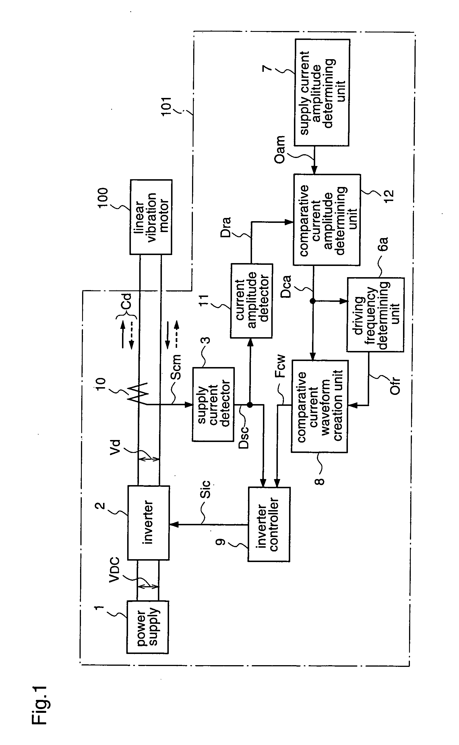
[0055]FIG. 1 is a block diagram for explaining a motor drive control apparatus according to the first embodiment of the present invention.

[0056]A motor drive control apparatus 101 according to the first embodiment performs feedback drive control for a linear vibration motor 100 which has a stator and a mover, and supports the mover with a spring so as to form a spring vibration system including the mover, on the basis of a comparative current waveform (first AC current waveform) as a reference of a driving current of the linear vibration motor 100. One of the stator and the mover comprises an electromagnet while the other comprises an electromagnet or a permanent magnet.

[0057]More specifically, the motor drive control apparatus 101 includes: a power source 1 for generating a DC voltage VDC as a power supply voltage; an inverter 2 for converting the power supply voltage VDC into an AC voltage Vd of a predetermined frequency, and supplying the converted AC voltage Vd to the linear vib...

second embodiment

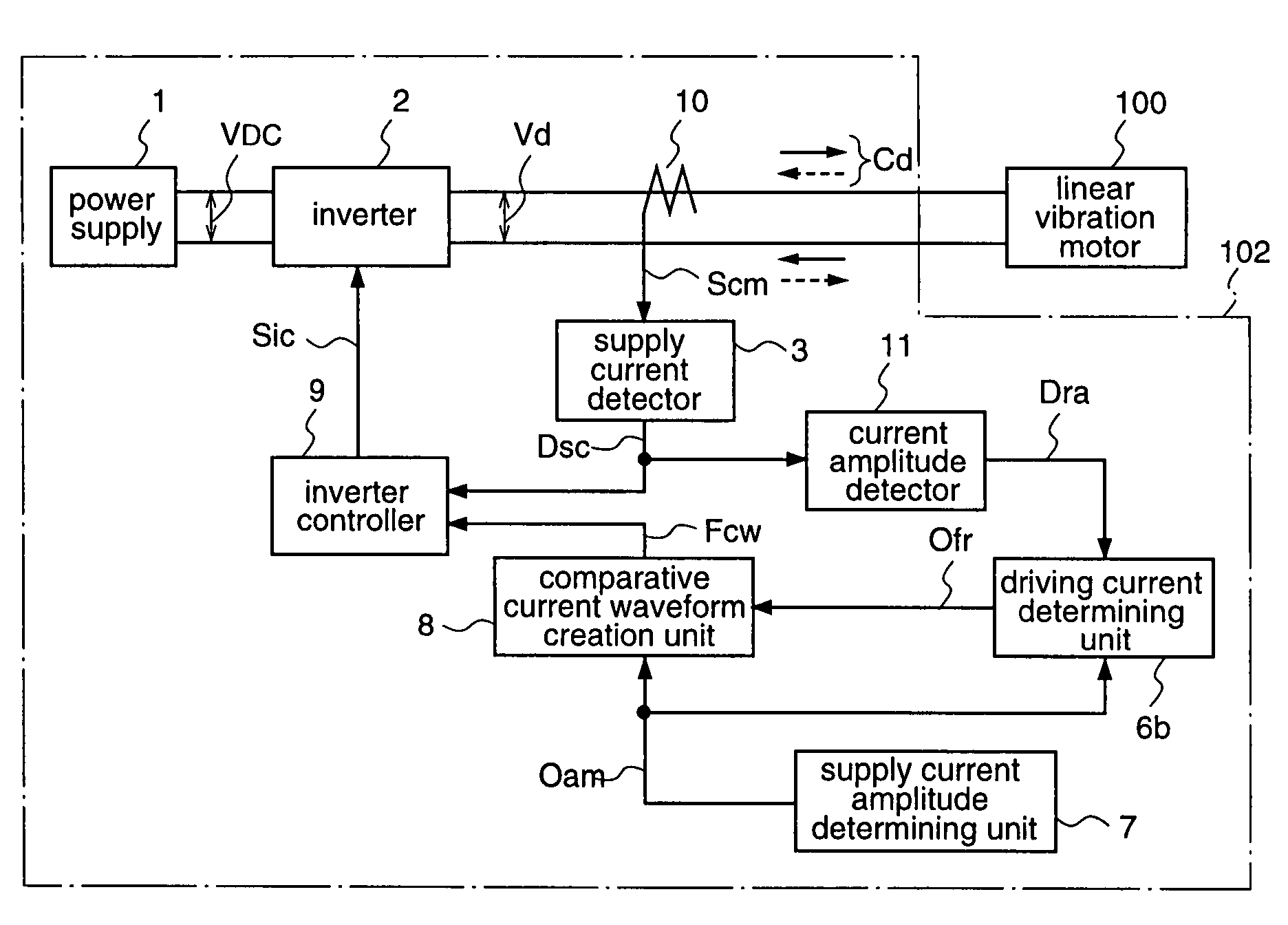
[0132]FIG. 4 is a block diagram illustrating a motor drive control apparatus according to a second embodiment of the present invention.

[0133]A linear vibration motor drive control apparatus 102 according to the second embodiment is provided with, instead of the comparative current amplitude value determining unit 12 and the driving frequency determining unit 6a of the first embodiment, a driving frequency determining unit 6b for determining a driving frequency ω of the inverter supply voltage Vd on the basis of the target amplitude value i″ of the inverter supply current Cd that is determined by the supply current amplitude determining unit 7 and the actual amplitude value i of the inverter supply current Cd that is detected by the current amplitude detector 11.

[0134]A power supply 1, an inverter 2, a supply current detector 3, a supply current amplitude determining unit 7, a comparative current waveform creation unit 8, an inverter controller 9, a current sensor 10, and a current a...

third embodiment

[0166]FIG. 7 is a block diagram for explaining a motor drive control apparatus according to a third embodiment of the present invention.

[0167]A motor drive control apparatus 103 according to the third embodiment performs feedback drive control of a linear vibration motor 100 having a stator and a mover, which is supported with a spring so as to form a spring vibration system including the mover, on the basis of a driving voltage and a driving current of the linear vibration motor 100, similar to the motor drive control apparatus 101 according to the first embodiment. This third embodiment is different from the first embodiment in that the frequency of an AC current as the driving current is determined on the basis of a power applied to the linear vibration motor 100, whereas the frequency of an AC current as the driving current is determined on the basis of the driving current of the linear vibration motor in the first embodiment. One of the stator and the mover comprises an electro...


PUM


Abstract

A motor drive control apparatus for driving and controlling a linear vibration motor having a mover supported by a spring, with an AC current. The motor drive control apparatus includes a waveform creation unit for creating a comparative current waveform to be a reference of a driving current for the linear vibration motor based on the operating condition of the linear vibration motor, a current detector for detecting the driving current, and a controller for controlling a driving voltage of the linear vibration motor so that a difference between the comparative current waveform and a waveform of the current detected by the current detector becomes zero. The frequency of the driving current is controlled to be close to the resonance frequency of the linear vibration motor, based on the comparative current waveform. Accordingly, the driving frequency of the linear vibration motor can always be brought to the resonance frequency without using a sensor for detecting a displacement, speed, or acceleration of the mover, for example.

Description

TECHNICAL FIELD OF THE INVENTION[0001]The present invention relates to a motor drive control apparatus and, more particularly, to a motor drive control apparatus for controlling a linear vibration motor on the basis of its driving current, thereby to drive the motor with high efficiency.BACKGROUND ART[0002]Conventionally, linear motors have been used as sources of reciprocating vibrations (refer to Japanese Published Patent Application No. Hei.2-52692 (FIG. 1)). This literature discloses a linear motor for generating a reciprocating vibration (hereinafter referred to as a linear vibration motor).[0003]The linear vibration motor is constructed as a single-phase sync motor having a mover comprising a rod-shaped permanent magnet, and a stator comprising an electromagnet. The electromagnet is obtained by winding a coil around both ends of a U-shaped iron core.[0004]An output voltage from an AC power supply is converted into a full-wave rectified voltage having a frequency twice as high ...

Claims


Application Information

Patent Timeline
Patent Type & Authority Patents(United States)
IPC IPC(8): H02P1/00F25B1/02H02P7/00H02P25/02H02P25/06H04M1/02
CPCH02P25/027H02P25/032
Inventor UEDA, MITSUONAKATA, HIDEKIYOSHIDA, MAKOTO
Owner PANASONIC CORP
Why Eureka
Try Eureka