Methods and apparatuses for memory array leakage reduction using internal voltage biasing circuitry

a technology of internal voltage biasing and memory array, applied in the field of memory, can solve the problems of memory consumption, power consumption, and power consumption of memory, and achieve the effect of reducing leakage current and reliably maintaining volatile memory cells

Active Publication Date: 2006-12-12
SYNOPSYS INC
View PDF50 Cites 23 Cited by
  • Summary
  • Abstract
  • Description
  • Claims
  • Application Information

AI Technical Summary

Benefits of technology

[0007]Various methods, apparatuses, and systems are described in which a volatile memory that includes a plurality of volatile memory cells as well as a voltage limiting component and a current limiting component. Power consumption in a standby mode is controlled. The voltage limiting component and the current limiting component couple between the volatile memory cells and the ground voltage potential. One or more rows of memory cells in the memory array are isolated from the ground voltage potential to control power consumption in the standby mode by having the current limiting component stop passing current in th

Problems solved by technology

Power consumption carries the heavy burden of impacting battery life on these portable devices such as cellular phones and PDAs.
Memories consume power even when in a standby mode and are not actively contributing anything to the operation of these portable devices.
Standby power dissipation for most CMOS circuits can be due to leakage currents.
Also, source line to bit line coupling can cause an adjacent bit line to drop in voltage level.
However, these memory array

Method used


Image

  • Methods and apparatuses for memory array leakage reduction using internal voltage biasing circuitry
  • Methods and apparatuses for memory array leakage reduction using internal voltage biasing circuitry
  • Methods and apparatuses for memory array leakage reduction using internal voltage biasing circuitry

Examples


Embodiment Construction

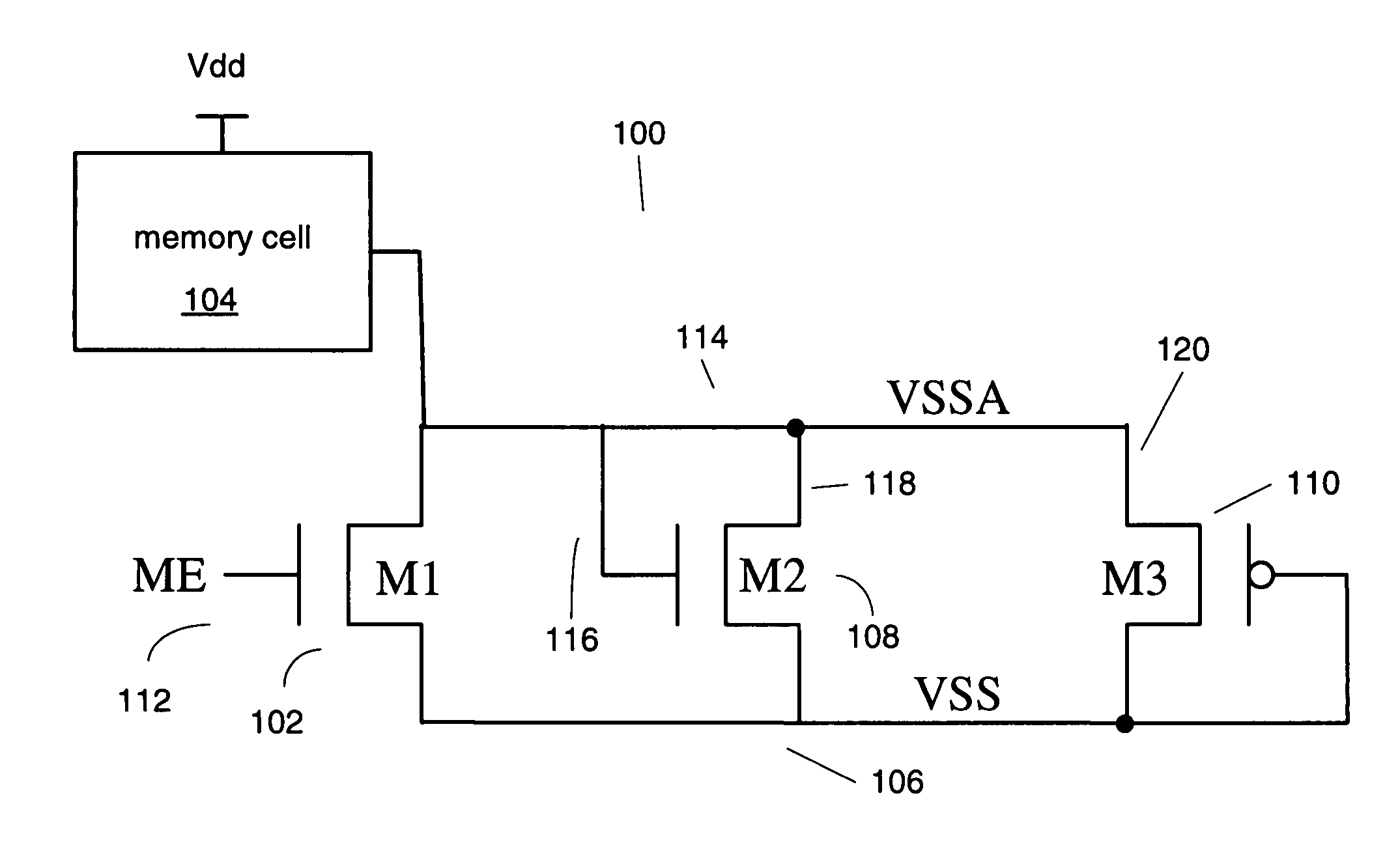
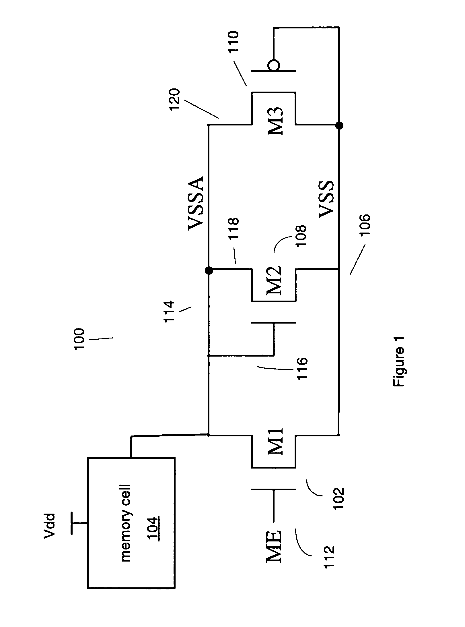
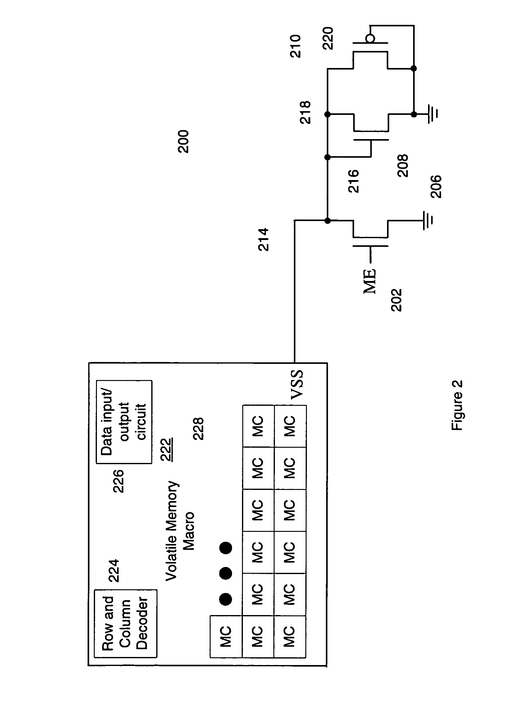
[0015]In the following description, numerous specific details are set fourth, such as examples of specific data signals, named components, connections, number of memory cells in a memory array, etc., in order to provide a thorough understanding of the present invention. It will be apparent, however, to one of ordinary skill in the art that the present invention may be practiced without these specific details. In other instances, well known components or methods have not been described in detail but rather in a block diagram in order to avoid unnecessarily obscuring the present invention. Further specific numeric references such as first transistor, may be made. However, the specific numeric reference should not be interpreted as a literal sequential order but rather interpreted that the first transistor is different than a second transistor. Thus, the specific details set fourth are merely exemplary. The specific details may be varied from and still be contemplated to be within the ...


PUM


Abstract

Various methods, apparatuses, and systems are described in which a volatile memory that includes a plurality of volatile memory cells as well as a voltage limiting component and a current limiting component. Power consumption in a standby mode is controlled. The voltage limiting component and the current limiting component couple between the volatile memory cells and the ground voltage potential. One or more rows of memory cells in the memory array are isolated from the ground voltage potential to control power consumption in the standby mode by having the current limiting component stop passing current in the standby mode. A floating ground voltage potential sensed by each memory cell when in the standby mode is controlled by configuring the voltage limiting component to conduct when the floating ground voltage potential is larger than a threshold voltage of the voltage limiting component in order to reduce leakage current but reliably maintain the stored contents of the volatile memory cell. The floating ground voltage potential is internally raised higher than a voltage biasing the bulk of the transistors in the volatile memory cells by coupling the floating ground voltage potential to the voltage limiting component.

Description

FIELD OF THE INVENTION[0001]Embodiments of the invention generally relate to memories. More particularly, an aspect of an embodiment of the invention relates to a volatile memory that reduces leakage current.BACKGROUND OF THE INVENTION[0002]Wireless and mobile devices depend upon various key requirements, such as minimizing power usage. Power consumption carries the heavy burden of impacting battery life on these portable devices such as cellular phones and PDAs. Maximizing the amount of battery life is very important while being able to maintain performance and minimize cost. Memories consume power even when in a standby mode and are not actively contributing anything to the operation of these portable devices. Also, the percentage of memory elements on a chip is rising. The combination of these two trends suggest that leakage reduction may be required in memory elements when the overall power consumption of the chip is a concern.[0003]Power dissipation in embedded SRAMs fall into ...

Claims


Application Information

Patent Timeline
IPC IPC(8): G11C5/14
CPCG11C11/412
Inventor FISHER, LOUIS CAMERONBRUMITT, CHARLES JEREMY
Owner SYNOPSYS INC
Why Eureka
Try Eureka