Cooperating array of micromirror devices for wireless optical communication

a technology of optical communication and micromirrors, applied in the field of optical communication, can solve the problems of high-frequency communication that cannot travel the distance that can be achieved by high-frequency communications, and the deployment of each of these conventional communications facilities involves certain limitations, so as to achieve accurate steering of a relatively large optical beam

Inactive Publication Date: 2006-12-12
TEXAS INSTR INC
View PDF4 Cites 12 Cited by
  • Summary
  • Abstract
  • Description
  • Claims
  • Application Information

AI Technical Summary

Benefits of technology

[0014]It is therefore an object of the present invention to provide a mirror assembly, and methods of fabricating and using the same, that can accurately steer a relatively large optical beam in the communication of optical data.

Problems solved by technology

Each of these conventional communications facilities involves certain limitations in their deployment.
In the case of communications over the telephone network, high-speed data transmission, such as that provided by digital subscriber line (DSL) services, must be carried out at a specific frequency range to not interfere with voice traffic, and is currently limited in the distance that such high-frequency communications can travel.
This physical installation and maintenance is costly, as well as limiting to the user of the communications network.
Conventional wireless technologies involve their own limitations, however.
For example, in the case of wireless telephony, the frequencies at which communications may be carried out are regulated and controlled; furthermore, current wireless telephone communication of large data blocks, such as video, is prohibitively expensive, considering the per-unit-time charges for wireless services.
Additionally, wireless telephone communications are subject to interference among the various users within the nearby area.
Radio frequency data communication must also be carried out within specified frequencies, and is also vulnerable to interference from other transmissions.
Satellite transmission is also currently expensive, particularly for bidirectional communications (i.e., beyond the passive reception of television programming).
As opposed to fiber optic-based optical communications, however, this approach does not use a physical wire or waveguide for transmission of the light signal.
However, practical and regulatory limits on the power density of the transmitted beam in turn limit the signal energy that may be communicated using these single beam steering elements.
For example, an important power density limit is that defining the “eye-safe” power density of the transmitted beams; use of a power density above this limit requires significant facility modifications (e.g., warning lights, eye protection, etc.), which are inconsistent with use of the system for data communications in office and building-to-building environments.
As known in the telescope art, however, the construction of accurate mirrors with larger diameters is an increasingly difficult task.
As such, according to conventional technology, it becomes very costly to increase the signal power of an optical communications beam while maintaining the power density below safety and other limits.

Method used


Image

  • Cooperating array of micromirror devices for wireless optical communication
  • Cooperating array of micromirror devices for wireless optical communication
  • Cooperating array of micromirror devices for wireless optical communication

Examples


Embodiment Construction

[0038]The present invention will be described in connection with its preferred embodiments, with an example of an application of these preferred embodiments in a communications network. It is contemplated, however, that the present invention may be realized not only in the manner described below, but also by way of various alternatives which will be apparent to those skilled in the art having reference to this specification. It is further contemplated that the present invention may be advantageously implemented and used in connection with a variety of applications besides those described below. It is therefore to be understood that the following description is presented by way of example only, and that this description is not to be construed to limit the true scope of the present invention as hereinafter claimed.

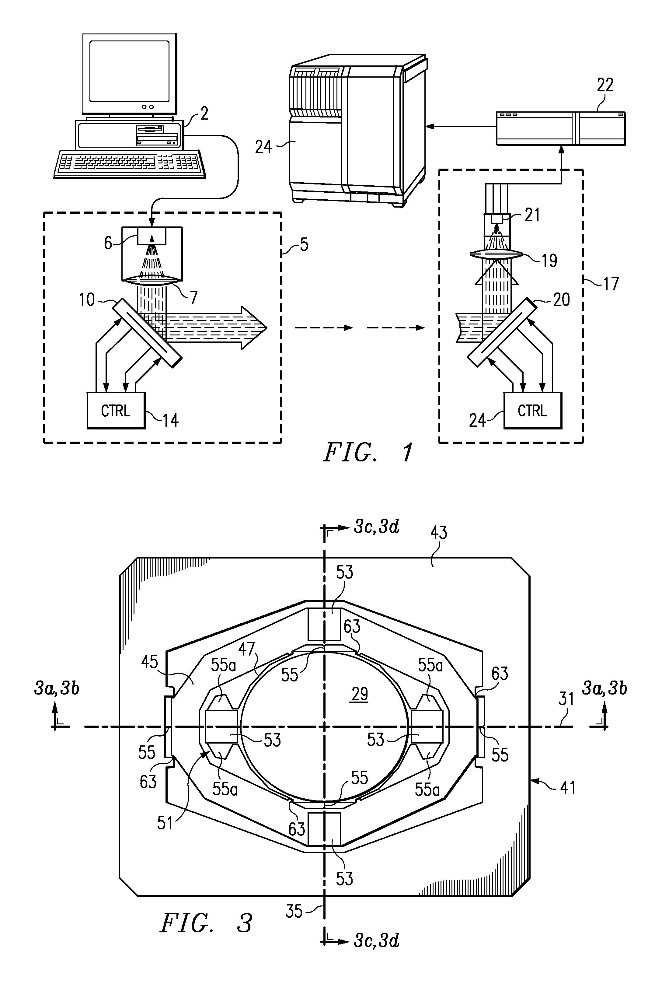
[0039]Referring first to FIG. 1, an example of an optical wireless network will be illustrated, to provide context for the present invention. In this simple example, unidire...


PUM


Abstract

A micromirror array assembly (10, 20) for use in optical modules (5, 17) in a wireless network system is disclosed. The micromirror array assembly (10, 20) includes a plurality of mirrors (29) monolithically formed with a frame (43), attached by way of hinges (55) and gimbal portions (45). Permanent magnets (53) are attached to each of the gimbal portions (45) associated with the mirrors (29). The resulting frame (43) is then mounted to a coil driver assembly (50) so that coil drivers (34) can control the rotation of each mirror (29), under separate control from control circuitry (14, 24). The micromirror array assembly (10, 20) is thus able to support higher signal energy at larger spot sizes, and also enables multiplexed transmission and receipt, as well as sampling of the received beam for quality sensing. A method of manufacturing the micromirror array assembly (10, 20) is also disclosed, in which a support wafer (60) is temporarily bonded to the mirror wafer (70) while the permanent magnets (53) are attached.

Description

[0001]This application claims priority under 35 USC. § 119 (e) (1) of Provisional Application No. 60 / 256,427, filed Dec. 18, 2000.CROSS-REFERENCE TO RELATED APPLICATIONS[0002]This application is related to copending provisional application Ser. No. 60 / 256,424 (TI-41588P), filed contemporaneously herewith, entitled “Method of Fabricating a Cooperating Array of Rotatable Microstructure Devices”, and commonly assigned herewith.STATEMENT REGARDING FEDERALLY SPONSORED RESEARCH OR DEVELOPMENT[0003]Not applicable.BACKGROUND OF THE INVENTION[0004]This invention is in the field of optical communications, and is more specifically directed to micromirror assemblies as used in such communications.[0005]Modern data communications technologies have greatly expanded the ability to communicate large amounts of data over many types of communications facilities. This explosion in communications capability not only permits the communications of large databases, but has also enabled the digital communi...

Claims


Application Information

Patent Timeline
Patent Type & Authority Patents(United States)
IPC IPC(8): H04J14/00
CPCG02B26/085G02B26/101
Inventor DEWA, ANDREW S.KELLER, ROBERT C.
Owner TEXAS INSTR INC
Why Eureka
Try Eureka