
Method and apparatus for equalization across plural data channels

Active Publication Date: 2006-12-12
CIENA
View PDF27 Cites 26 Cited by
  • Summary
  • Abstract
  • Description
  • Claims
  • Application Information

AI Technical Summary

Benefits of technology

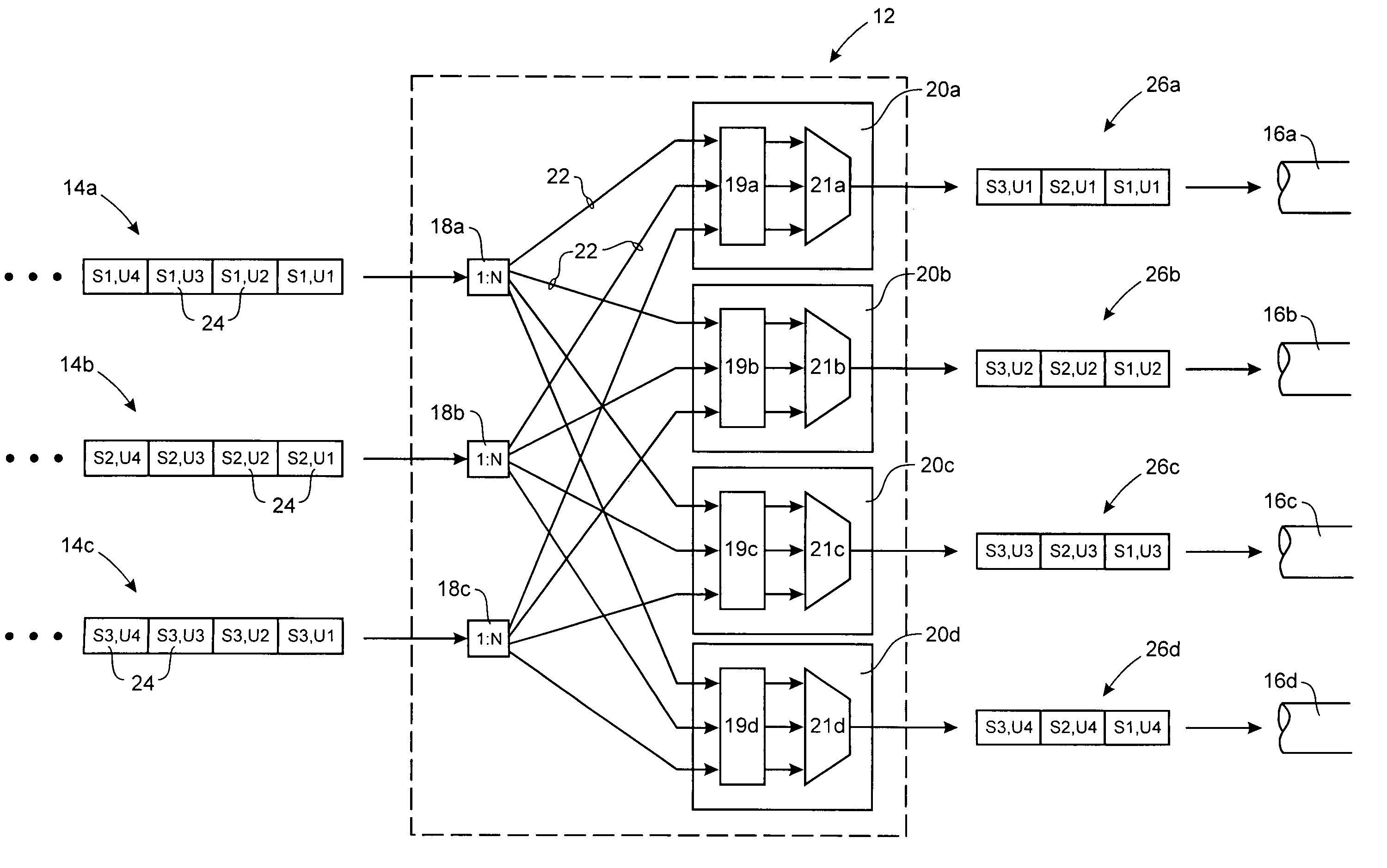
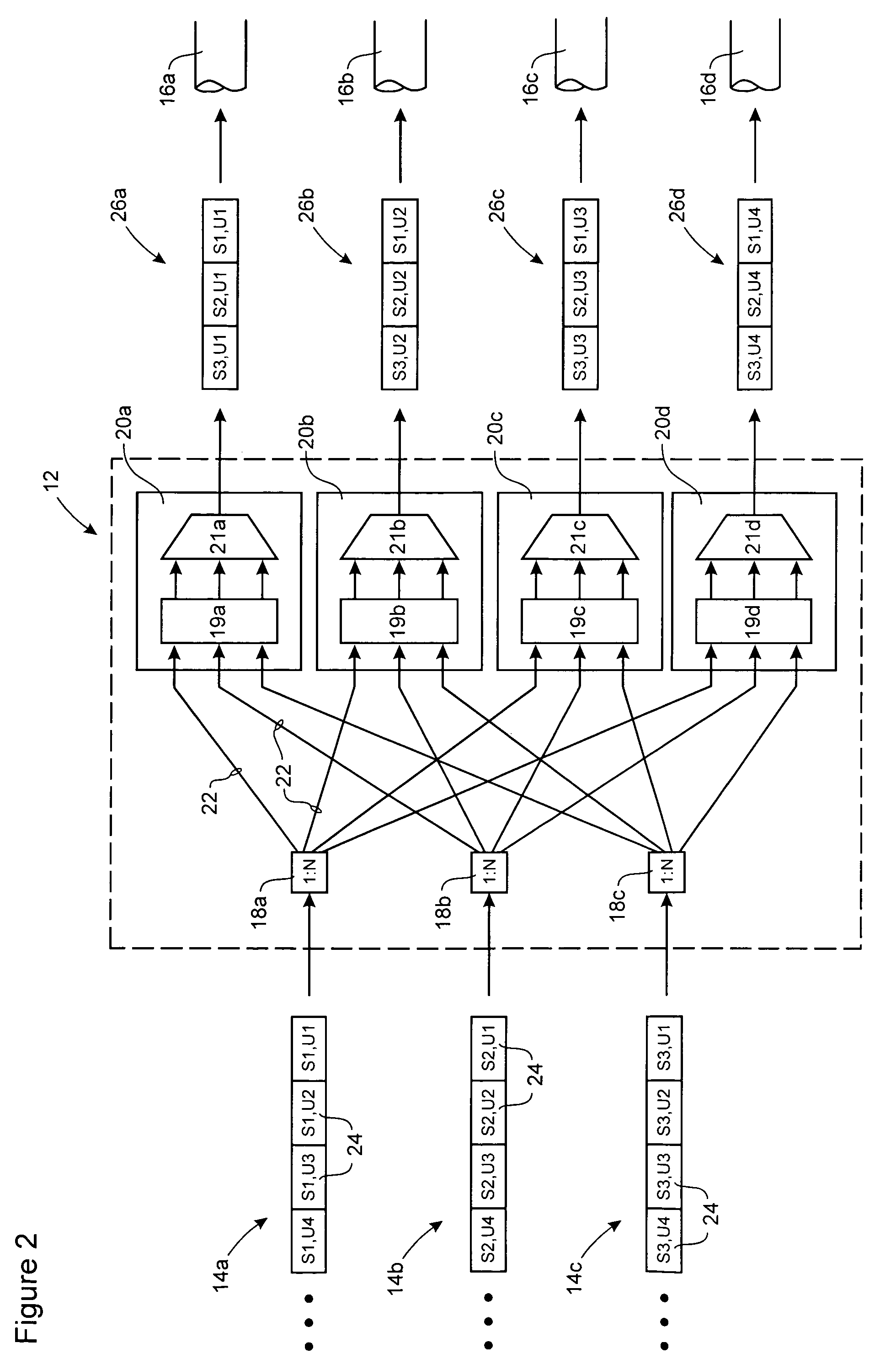
[0025]An advantage of the present invention resides in the recognition that it is the bit error rate of data signals being transported through a fiber link, rather than the bit error rate of any one channel, that should be determinative of link length. By distributing each data signal evenly across two or more channels, the bit error rate for the signal is an average of the bit error rates of each involved channel. Thus the impact of any variations in channel performance is shared equally by each of the data streams, thereby diluting the effects of the lowest-performing channel and consequently allowing an increase in link length beyond that which would be indicated by the bit error rate of the lowest-performing channel.
resides in the recognition that it is the bit error rate of data signals being transported through a fiber link, rather than the bit error rate of any one channel, that should be determinative of link length. By distributing each data signal evenly across two or more channels, the bit error rate for the signal is an average of the bit error rates of each involved channel. Thus the impact of any variations in channel performance is shared equally by each of the data streams, thereby diluting the effects of the lowest-performing channel and consequently allowing an increase in link length beyond that which would be indicated by the bit error rate of the lowest-performing channel.

Problems solved by technology

In the modern communications network space, signal reach and spectral density are important factors in overall network cost.
However, there is a trade-off involved in using increased line rates to improve spectral density.
This reduction in signal reach is explained by the fact that, as the line rate increases non-linear optical effects (e.g. self-phase modulation, optical dispersion, etc.) become progressively more significant, and cause increased bit error rates.
While each of the above methods are capable of reducing variations in gain, the physical properties of installed equalization devices are subject to a certain amount of variation, resulting in an unavoidable equalization error, typically on the order of approximately +0.2 dB.

Method used


Image

  • Method and apparatus for equalization across plural data channels
  • Method and apparatus for equalization across plural data channels
  • Method and apparatus for equalization across plural data channels

Examples


Embodiment Construction

[0031]The present invention provides a method and apparatus for optical equalization to improve signal reach by distributing two or more data signals across two or more channels of an optical link. At a receiving end of the optical link, data-streams conveyed through each of the channels are processed to recover the original data signals.

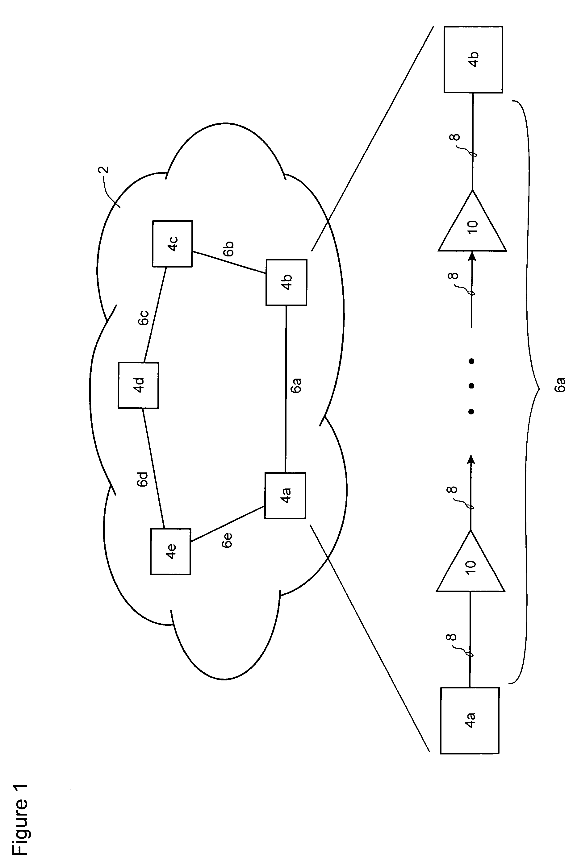
[0032]FIG. 1 is a schematic diagram of a communications network 2 in which the present invention may be deployed. The network 2 includes a plurality of nodes 4a–e (which may be, for example, routers, cross-connects, regenerators or Add-Drop-multiplexors (ADMs)) interconnected by fibre links 6a–e. Each of the nodes 4a–e are preferably electro-optical nodes configured for wave division multiplex (WDM) and / or dense wave division multiplex (DWDM) transport of data traffic. For the purposes of the present invention, optical signals received at a node 4 from a fiber link 6 are assumed to be de-multiplexed and converted to electrical signals for signal reg...


PUM


Abstract

Optical equalization across N (an integer, N>1) channels of a multi-channel link of a communications network, is accomplished by averaging effects of optical performance variations within each of the M (an integer, M>1) parallel data signals. At a transmitting end node of the link, each one of the M data signals are distributed across the N channels of the link. Thus a substantially equal portion of each data signal is conveyed through the link in each one of the N channels. At a receiving end node of the link, respective bit-streams received over the N channels to are processed recover the M data signals. As a result, bit error rates of the bit-streams received through each channel are averaged across the M data signals, all of which therefore have a substantially equal aggregate bit error rate.

Description

CROSS-REFERENCE TO RELATED APPLICATIONS[0001]This is the first application filed for the present invention.MICROFICHE APPENDIX[0002]Not Applicable.TECHNICAL FIELD[0003]The present invention relates to communications networks, and in particular to a method and apparatus for signal equalization across multiple data channels of an optical communications network.BACKGROUND OF THE INVENTION[0004]In the modern communications network space, signal reach and spectral density are important factors in overall network cost. Assuming other factors to be equal, increases in either signal reach or spectral density tend to reduce overall network cost and are thus very attractive to network service providers.[0005]Signal reach is the distance that an optical signal can be transmitted through a fiber, before conversion to electronic form is required to perform signal regeneration. Using suitable optical amplifiers and optical processing techniques, between 10 and 20 fiber spans (of 40–80 km each) ca...

Claims


Application Information

Patent Timeline
IPC IPC(8): H04B10/00
CPCH04J14/02
Inventor SMITH, ROLAND A.ROBERTS, KIM B.
Owner CIENA
Learn More