Integrated information communication system using internet protocol

Inactive Publication Date: 2006-12-12
THE DISTRIBUTION SYST RES INST
29 Cites 11 Cited by

AI-Extracted Technical Summary

Problems solved by technology

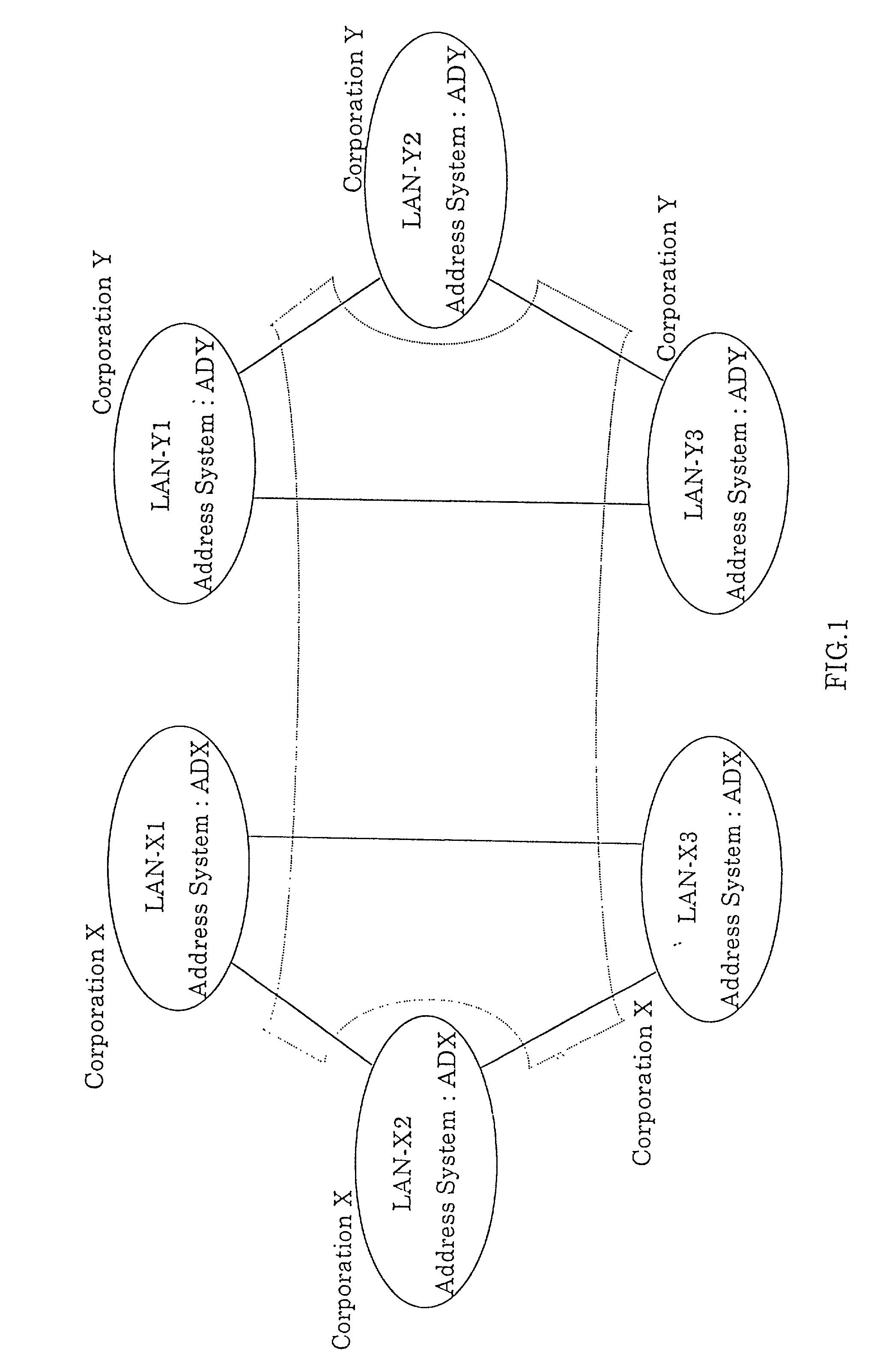
Since it is necessary to lay a separate dedicated line for each corporation with such a LAN network, system architecture becomes costly, and in the event that connection is to be made to a LAN network of another corporation, interfacing must be matched such as the communication address system, making inter-connection very difficult and very costly.
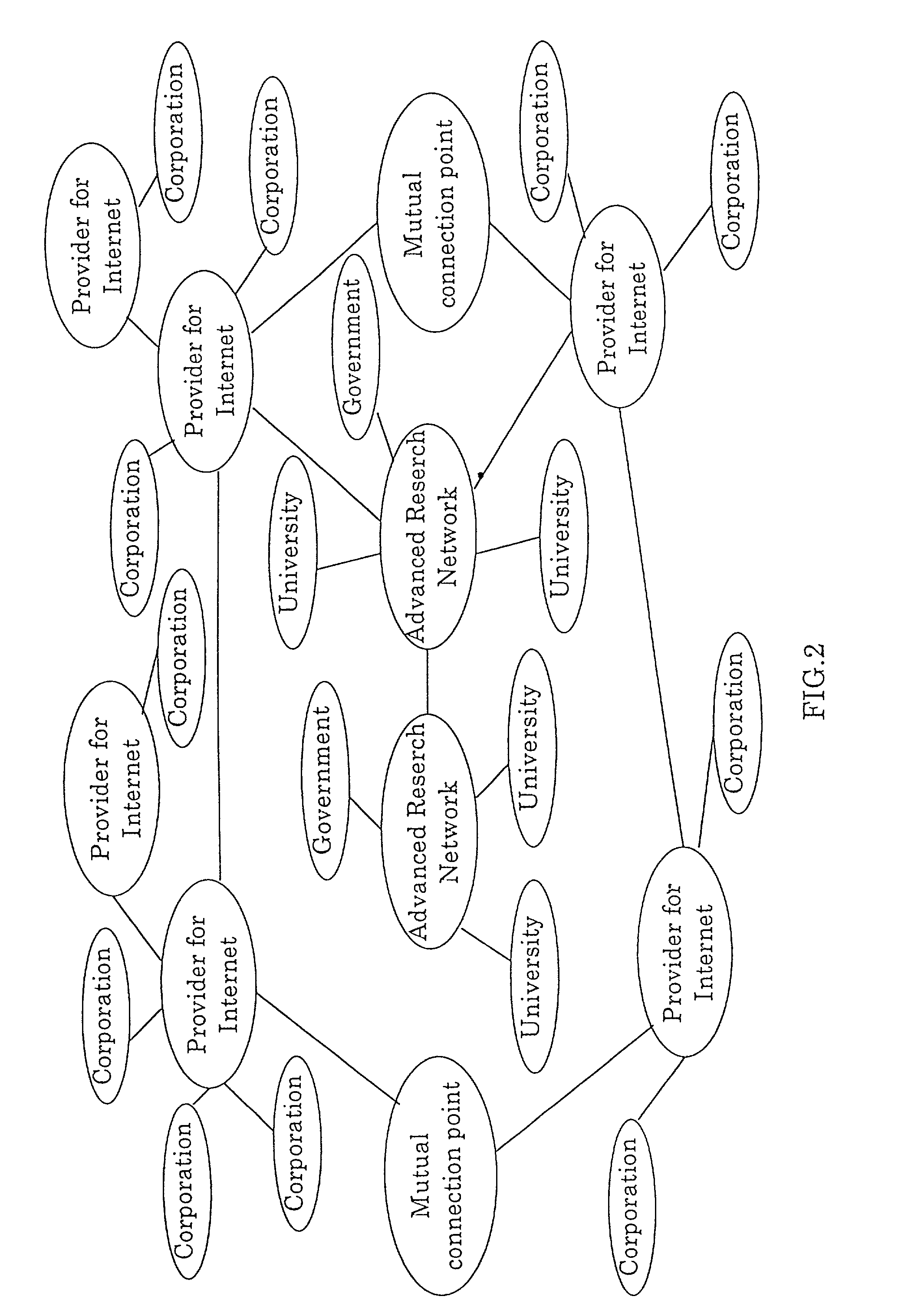
However, with the Internet, since the system is such that the communication path is not administrated in an integrated manner, one cannot tell whether the other party with which communication is being made is the authorized party, and there are problems regarding security in that information may be eavesdropped.
Also, communication quality such as communication speeds and communication error rates for the trunk lines making up the Internet communication...

Benefits of technology

[0009]The present invention has been made in accordance with the above-described situations, and it is an object of the present invention to provide an integrated information communication system capable of containing a plurality of VANs (Value Added Networks) which perform data/information transfer by using IP frame of which security and reliability in communications has been ensured, by means of not using dedicated lines or the Internet so as to improve economic considerations of the information communication system architecture, and ensuring communication speeds, communication quality and communication trouble countermeasures in a unified manner. Also, it is another object of the present invention to provide an integrated information communication system which uses a si...

Abstract

The integrated information communication system is comprised of an access control apparatus for connecting a plurality of computer communication networks or information communication equipment to each, and a relay device for networking the aforementioned access control apparatus. The system has functions for performing routing by transferring information by a unified address system and by changing address at the access control apparatus, and is configured such that the aforementioned plurality of computer communication networks or information communication equipment can perform communications in an interactive manner. The integrated information communication system ensures communication speed, communication quality, communication trouble countermeasures in a unified manner, without using dedicated lines or the Internet, wherein security and reliability in communication is ensured without change of a private address system.

Application Domain

Multiple digital computer combinationsTransmission +1

Technology Topic

Communication qualitySwitched communication network +11

Image

  • Integrated information communication system using internet protocol
  • Integrated information communication system using internet protocol
  • Integrated information communication system using internet protocol

Examples

  • Experimental program(17)

Example

Embodiment-1
Basic ICS, Intra-Corporation Communication and Inter-Corporation Communication

Example

[0117]A first embodiment of the present invention will be described with reference to FIGS. 14 and 15, regarding a basic communication wherein the transfer destination within the ICS is determined from the receiver ICS user address, based on administration by a conversion table. In the figures, 170-1, 170-2, 170-3 and 170-4 respectively denote gateways provided within the LANs 100-1, 100-2, 100-3 and 100-4, and the ICS frames can pass through these gateways 170-1 through 170-4. FIG. 16 shows an example of a conversion table 113-1 in the access control apparatus 111-1 and FIG. 17 does the same of a temporary conversion table 114-2 in the access control apparatus 110-4.
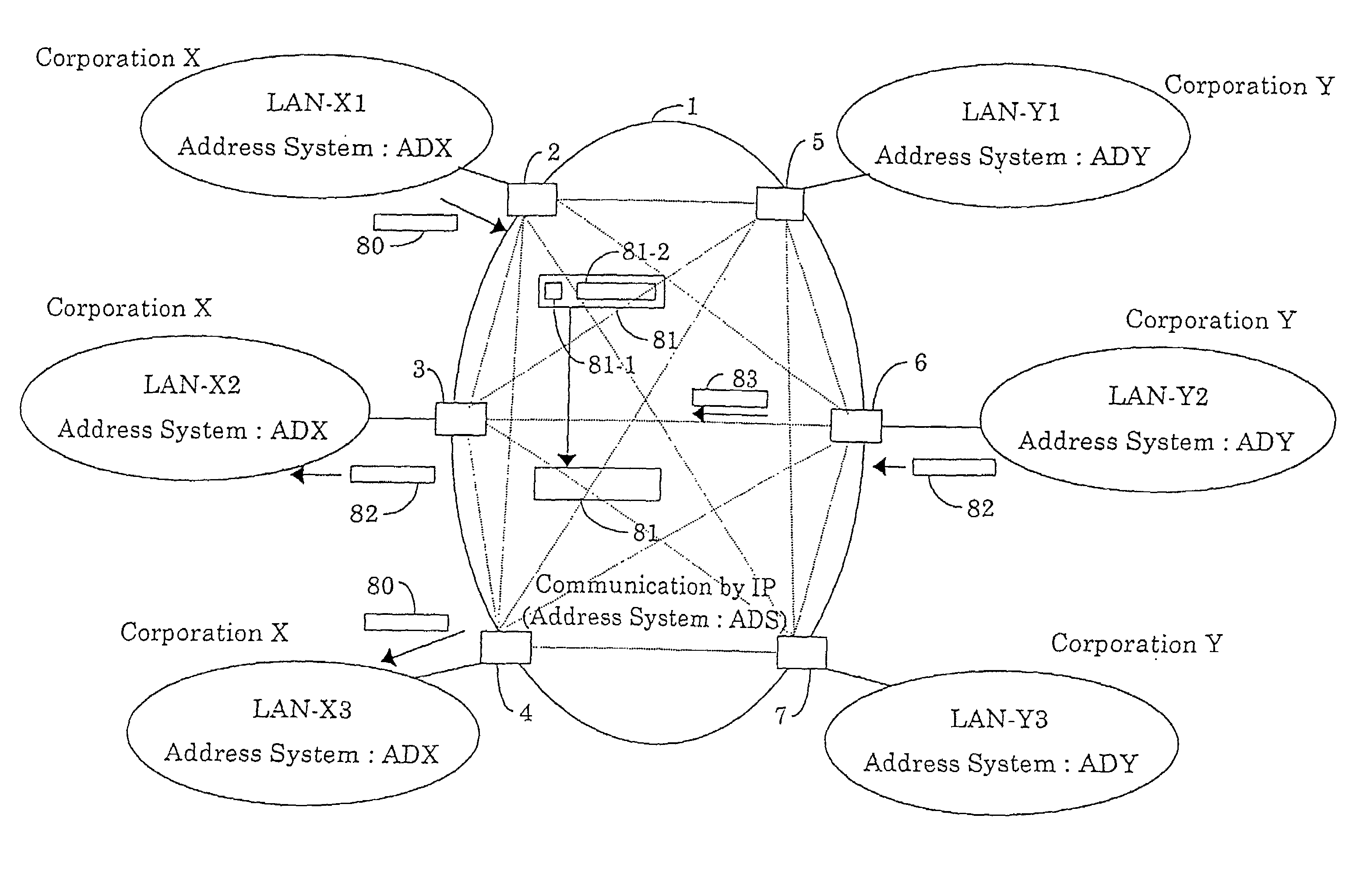
[0118]First, description will be made regarding communication between a terminal which is connected to a LAN 100-1 of the corporation X which has a unique address system ADX, and a terminal which is connected to a LAN 100-2 of the same corporation X. That is, this is a communication between a terminal which has an ICS user address “0012” on the LAN 100-1 and a terminal which has an ICS user address “0034” on the LAN 100-2. This communication is a typical communication made between terminals which have set addresses based on a unique address system within a single corporation (ADX in this example), the communication being made via the ICS 100 in an interactive manner. This type of communication is referred to as intra-corporation communication service (or intra-corporation communication). Next, description will be made regarding a communication between a terminal which is connected to a LAN 100-1 of the corporation X which has a unique address system ADX and a terminal which is connected to a LAN 100-3 of the corporation Y which has a unique address system ADY. That is, this is a communication between a terminal which has an ICS user address “0012” on the LAN 100-1 and a terminal which has an ICS user address “1156” on the LAN 100-3. This communication is a typical communication made between terminals which have different address systems within different corporations, the communication being made using an ICS address system which can be shared between the two. This type of communication is referred to as inter-corporation communication service (or inter-corporation communication).
<>
[0119]In describing the present embodiment, the address format and so forth is determined as described below, but the specific numeric values and formats are all but an example, and the present invention is by no means limited to these. The ICS network address is represented by a 4-digit number, and the sender ICS user address and the receiver ICS user address are both represented by a 4-digit number. Of the sender ICS user address and the receiver ICS user address, addresses of which the upper two digits are not “00” are used as an inter-corporation communication address, and this inter-corporation communication address is an only value within the ICS 100. Of the sender ICS user address and the receiver ICS user address, addresses of which the upper two digits are “00” are used as an intra-corporation communication address, and this intra-corporation communication address may be duplicate of other intra-corporation communication address within the ICS 100. Also, the conversion table 113-1 in FIG. 16 provided to the access control apparatus 110-1 contains the following: transmitting ICS network addresses, receiving ICS network addresses, sender ICS network addresses, receiver ICS network addresses, request identification (ID), speed segments and so forth. The request identification registered to the conversion table 113-1 is such that, e.g., “1” represents the intra-corporation communication service, “2” represents the inter-corporation communication service, and “3” represents a virtual dedicated line connection (which will be descrived hereinafter). The speed segment is the line speed that the communication from the ICS network address requires, including throughput (e.g., the number of ICS frames sent within a predetermined time).
<>
[0120]The users of the LAN 100-1 and the LAN 100-2 specify the terminals and apply to the VAN operator in order that the intra-corporation communication of the terminals connected to the LANs can perform the communication via the VAN-1 and VAN-3. The VAN operator responds to the application and sets the aforementioned ICS network address, ICS user address, requested identification, etc. to the conversion tables of the access control apparatuses 110-1 and 110-5 connected to the LAN 100-1 and LAN 100-2, and further writes and holds them in the ICS address administration server 150-1.
[0121]The items to be set for the VAN-1 are as follows. The ICS network address is decided by the ICS logic terminal of the access control apparatus 110-1 to which the LAN 100-1 is connected, with the ICS network address of the ICS logic terminal in this case being set as “7711”. The intra-corporation communication address of the terminal connected to the LAN 100-1 from which the application was made is set as “0012”, and this is used as the sender ICS user address. The intra-corporation communication address used by the terminal of the above address is set as “2212”, and this is used as the sender ICS user address. Next, the intra-corporation communication address of the terminal connected to the LAN 100-2 from which the application was made is decided by the ICS logic terminal of the access control apparatus 110-5 to which the LAN 100-2 is connected, in this case the ICS network address being set as “9922”, and this is used as the receiving ICS network address. Further, the ICS user address used by the terminal connected to the LAN 100-2 is set as “0034”, and this is used as the receiver ICS user address. The number “1” is set as the request identification, indicating the intra-corporation communication service that was applied for, and the above is registered to the conversion table 113-1 in FIG. 16.
[0122]The items to be set for the VAN-3 are as follows. Values necessary for reverse communication (communication from the LAN 100-2 to the LAN-1) are set to the conversion table of the access control apparatus 110-5 connecting the LAN 100-2 from which application was made. That is, data is set reverse to the transmitting ICS network address and the receiving ICS network address, and at the same time, data is set reverse to the sender ICS user address and the receiver ICS user address. The ICS network address of the LAN 100-2 is set as “9922”, and this is used as the transmitting ICS network address. The address “0034” is set as the sender ICS user address for the intra-corporation ICS user address of the terminal connected to the LAN 100-2, and the ICS user address “0012” of the terminal of the other party is used as the receiver ICS user address. Also, the ICS user address “7711” of the LAN 100-1 is used as the receiving ICS network address and the value “1” is set as the request identification, indicating the intra-corporation communication services. The above is written to the conversion table in the access control apparatus 110-5 and registered.
<>
[0123]The terminal having an ICS user address “0012” sends an ICS user frame P1 to the receiver “0034”. This ICS user frame P1 has set as the sender ICS user address “0012”, and as the receiver ICS user address has set “0034”.
[0124]The operation will be explained with reference to FIG. 18. The ICS user frame P1 is sent to the access control apparatus 110-1 via the logic communication line 180-1. The access control apparatus 110-1 refers to the conversion table 113-1 of FIG. 16 from the transmitting ICS network address “7711” (Steps S100 and S101) and the receiver ICS user address “0034” of the received ICS user frame, it knows that the communication is the intra-corporation communication due to the value “1” of the request identification (Step S102). The access control apparatus 110-1 obtains that the receiving ICS network address corresponding to the receiver ICS user address “0034” is “9922”, and then it is ICS-encapsulized (Step S106). The above procedures illustrated in a flowchart are as shown in FIG. 18, with the intra-corporation being flow (1) therein. The sender ICS user address may be used to specify the transmitted original of the ICS frame.
[0125]The access control apparatus 110-1 sends the ICS network frame P2 to the relay apparatus 120-1 by the ICS encapsulation. Since the network address of the network control field is ensured of its uniqueness within the ICS, there is no conflict with other ICS frames. The ICS network frame P2 passes through the relay apparatus 120-1 and 120-2 based on the receiving ICS network address, and reaches the access control apparatus 110-5 of the VAN-3. The access control apparatus 110-5 removes the network control field from the ICS network frame P4 and performs the ICS reverse encapsulation, and re-creates an ICS user frame P5 which is the same as the ICS user frame P1 from the network data field of the ICS frame, and sends it to the LAN 100-2. The ICS user frame is routed through the LAN 100-2, and is transferred to the terminal which has the ICS user address “0034”.
<>
[0126]As an example of performing the inter-corporation communication, a communication between a terminal which has an ICS user address “0012” and is connected to a LAN 100-1 under the address system ADX, and a terminal which has an ICS user address “1156” and is connected to a LAN 100-3 under the address system ADY, will be described. The users of the LANs 100-1 and 100-3 specify the terminal to the VAN each is connected to so as to be able to perform the communication via VAN-1 and VAN-2, and make application to the VAN operator. The VAN operator sets the necessary items in the conversion table of the access control apparatus which is connected to the LANs 100-1 and 100-3, in accordance with the application.
[0127]The items to be set regarding the VAN-1 are as follows. The ICS network address of the LAN 100-1 is made to be “7711”, the intra-corporation communication address held by the terminal connected to the LAN 100-1 from which there was application is made to be “0012”, and this is made to be the sender ICS user address. The inter-corporation communication address provided to the terminal of the above ICS user address is made to be “2212”, and this is made to be the sender ICS user address (inter-corporation). The ICS network address is determined by the ICS logic terminal of the access control apparatus 110-4 connected to the ICS network address of the LAN 100-3 from which there was application, the ICS network address here being “8822”, and this is made to be the receiving ICS network address. Also, the ICS user address of a terminal connected to the LAN 100-3 is made to be “1156”, and this is made to be the receiver ICS user address. Further, number “2” is set as the request identification, indicating the inter-corporation communication service that was applied for, and the above is registered to the conversion table 113-1.
[0128]The items to be set regarding the VAN-2 are as follows. As a conversion table for the access control apparatus 110-4 to which the LAN 100-3 is connected, a temporary conversion table 114-2 which holds reverse data for a certain time, e.g., 24 hours, is set. That is, regarding the ICS network address “8822” to which is connected the LAN 100-3 which uses the inter-corporation communication service, the following are provided within the access control apparatus 110-4: a temporary conversion table 114-2 which includes a transmitting ICS network address, sender ICS user address, receiver ICS user address, receiving ICS network address, request identification and so forth. The setting of the temporary conversion table will be explained hereinafter.
<>
[0129]The terminal having an ICS user address “0012” transmits the ICS user frame F1 in which the sender ICS user address “0012” and the receiver ICS user address “1156” are set. The ICS user frame F1 is transferred to the access control apparatus 110-1 via the user logic communications line 180-1.
[0130]The access control apparatus 110-1 refers to the conversion table 113-1 from the transmitting ICS network address “7711” (Steps S100 and S101) and the receiver ICS user address “1156”, it knows that the request identification is “2”, that is, the communication is the inter-corporation communication (Step S102). Next, the access control apparatus 110-1 obtains that the receiving ICS network address corresponding to the receiver user address “1156” is “8822” (Step S104), and then converts the sender ICS user address “0012” into an inter-corporation communication user address “2212” (Step S105). The access control apparatus 110-1 performs the ICS encapsulation by adding a network control field as the transmitting ICS network address “7711”, the sender ICS user address “2212”, the receiver ICS user address “1156” and the receiving ICS network address “8822”, and sends it to the relay apparatus 120-1 as the ICS network frame F2 (Step S106). The above procedures illustrated in a flowchart are as shown in FIG. 18, with the inter-corporation communication being flow (2) therein.
[0131]In the above inter-corporation communication, in the event that the sender ICS user address within the ICS user frame F1 is made to be the inter-corporation communication address “2212”, the sender and receiver perform the inter-corporation communication using an inter-corporation communication address (Steps S102 and S104). In this case, the access control apparatus 110-1 does not perform the process of converting the sender ICS user address “2212” into the inter-corporation communication address “2212”, as such is not necessary. The above procedures are illustrated in a flowchart shown in FIG. 18, with the inter-corporation communication as flow (3). The sender ICS user address may be used to specify the transmitted original of the ICS frame.
[0132]The relay apparatus 120-1 transfers the ICS network frame to the access control apparatus 110-4 within the VAN-2 via the relay apparatus 120-2 within the VAN-1, the inter-VAN gateway 130, and the relay apparatus 120-3 within the VAN-2, based on the receiving ICS network address. It will be described with reference to FIG. 19. The access control apparatus 110-4 receives the ICS network frame (Step S110), forms an ICS user frame F5 from the network data field (Step S111: ICS reverse encapsulation), decides from the receiving ICS network address the ICS logic terminal for sending ((1) in Step S112), and sends to the LAN 100-3 (Step S113). At the same time, in the event that the relation among the transmitting ICS network address “7711”, the sender ICS user address “2212”, the receiver ICS user address “1156” and the receiving ICS network address “8822” is not registered in the conversion table within the access control apparatus 110-4, a temporary conversion table 114-2 is compiled ((2) in Step S112). The registration contents of the temporary conversion table 114-2 are updated according to a process such as the contents being deleted if there is no usage thereof for 24 hours. The ICS use frame is routed through the LAN 100-3, and is transferred to the terminal having the ICS user address “1156”.
[0133]In this embodiment, it is not set in the temporary conversion table 114-2. In another embodiment of this, the conversion table 113-1 does not include the sender ICS user address (intra-corporation) and the sender ICS user address (inter-corporation), and further does not contain the flowchart (2) in FIG. 18, i.e., Step S105. A merit of this embodiment is that the register number to the conversion table can be reduced to one of the sender ICS user address if there are the sender ICS user address for one of the receiver ICS user address.

Example

Embodiment-2
Virtual Dedicated Line
[0134]Now, description of the operation of virtual dedicated line connection according to the present invention will be made with reference to FIG. 20. Here, the virtual dedicated line connection refers to communication wherein the ICS user frame is transferred in a fixed manner to a receiving ICS network address already registered in the conversion table, regardless of the ICS user address within the user control field of the ICS user frame, in which the format taken is one-on-one or one-on-N. While the components of FIG. 20 are the same as those of Embodiment-1 shown in FIGS. 14 and 15, what is different is the contents of registration in the conversion table shown in FIG. 21. In the conversion table of the access control apparatus, the receiving ICS network address is determined from the transmitting ICS network address in a fixed manner, so that either the sender ICS user address (intra-corporation), the sender ICS user address (inter-corporation) and the receiver ICS user address are either not registered, or ignored if registered.
[0135]Description will now be given regarding a case in which the corporation X uses virtual dedicated line connection, and the communication is conducted between the LAN 200-1 of the corporation X which is connected to the access control apparatus 210-1, and the LAN 200-2 of the corporation X which is connected to the access control apparatus 210-5.
<>
[0136]The user applies to the VAN operator for the virtual dedicated line connection. The VAN operator determines the ICS network address “7711” of the ICS logic terminal at the connection point between the access control apparatus 210-1 for connecting the LAN 200-1 of the corporation X and the user logic communications line 240-1, and similarly determines the ICS network address “9922” of the ICS logic terminal at the connection point between the access control apparatus 210-5 for connecting the LAN 200-2 of the corporation X and the user logic communications line 240-2. Next, the VAN operator performs setting to the conversion table 213-1 of the access control apparatus 210-1 of the following: the transmitting ICS network address “7711”, the receiving ICS network address “9922” and the request identification. Illustrated in FIG. 21 is an example wherein the request identification “3” has been made to serve as the virtual dedicated line connection. Similarly, the VAN operator performs setting to the conversion table of the access control apparatus 210-5 of the following: the transmitting ICS network address “9922”, the receiving ICS network address “7711” and the request identification.
<>
[0137]The operation will be explained with reference to FIG. 22. The LAN 200-1 of the corporation X sends an ICS user frame F10 to the ICS 200 via the user logic communications line 240-1. The access control apparatus 210-1 receives the ICS user frame F10 from the ICS logic terminal of the ICS network address “7711” (Steps S200 and S201), references to the request identification “3” of the originating ICS network address “7711” in the conversion table 213-1, identifies this as a virtual dedicated line connection (Step S202), and reads the receiving ICS network address “9922” (Step S203). Next, the access control apparatus 210-1 adds a network control field to the ICS user frame F10 in which the receiving ICS network address is set to “9922” and the transmitting ICS network address is set to “7711”, thus forming an ICS network frame F11 (Step S204; ICS encapsulation), and sends the frame F1 to the relay apparatus 200-1 (Step S205). The relay apparatus 220-1 which received the ICS network frame F11 determines the destination based on the receiving ICS network address of the ICS network frame F11, and sends an ICS network frame F12 to the relay apparatus 220-2. The ICS network frame F12 is transferred to the access control apparatus 210-5 via the relay apparatus 220-4 within the VAN-3.
[0138]The access control apparatus 210-5 removes the network control field from the ICS network frame F13 (ICS reverse encapsulation), and sends the ICS network frame F14 from the ICS logic terminal of the ICS network address “9922” to the user logic communications line 240-2. Then, the LAN 200-2 of the corporation X receives the ICS user frame F14. Transmission can be made in the same say as described from the LAN 200-2 to the LAN 200-1, and thus, interactive communication is available. Since it is clear that the sender and the receiver are not necessary to be the same corporation X, using the same method, an ICS user frame can be transferred from the LAN 200-1 of the corporation X to a LAN 200-3 of another corporation Y.
[0139]While the above description has been made with reference to a case of one-on-one, one-on-N communication can also be performed. For example, a plurality of ICS network addresses may be set to the conversion table 213-1 of the access control apparatus 210-1 shown in FIG. 20, as indicated by the transmitting ICS network address “7712”. In the present example, two ICS network addresses “6611” and “8822” are set. The access control apparatus 210-1, upon receiving the ICS user frame from the ICS logic terminal with an ICS network address “7712”, forms a first ICS network frame wherein an ICS network control field set with “6611” for the receiving ICS network address is added thereto, and a second ICS network frame wherein a network control field set with “8822” for the receiving ICS network address is added thereto, these being sent to the relay apparatus 220-1. Consequently, one-on-two communication can be performed. Further, one-on-N communication can be performed by transferring each ICS network frame in the same manner as described above.

PUM

no PUM

Description & Claims & Application Information

We can also present the details of the Description, Claims and Application information to help users get a comprehensive understanding of the technical details of the patent, such as background art, summary of invention, brief description of drawings, description of embodiments, and other original content. On the other hand, users can also determine the specific scope of protection of the technology through the list of claims; as well as understand the changes in the life cycle of the technology with the presentation of the patent timeline. Login to view more.

Similar technology patents

Integrated information communication system using internet protocol

InactiveUS20060230182A1improve economic considerationlittle change
Owner:THE DISTRIBUTION SYST RES INST

Vehicle accelerator opening degree adjusting method and device

ActiveCN112009240Alittle changeAlgorithm is simple
Owner:BEIJING CO WHEELS TECH CO LTD

Method for synthesizing ammonia

InactiveCN107794089Alittle changeLow outlet temperature
Owner:陈全保

A delay adjustment circuit with adjustable range and step size

ActiveCN104579258Blittle change
Owner:CHENGDU CORPRO TECH CO LTD

Constant flow valve capable of automatically regulating oil fluid delivery flow

ActiveCN106224610AIncrease the openinglittle change
Owner:CHONGQING UNIVERSITY OF SCIENCE AND TECHNOLOGY

Classification and recommendation of technical efficacy words

  • improve economic consideration
  • little change

Integrated information communication system using internet protocol

InactiveUS20060230182A1improve economic considerationlittle change
Owner:THE DISTRIBUTION SYST RES INST

Plasmonic nano-color coating layer and method for fabricating the same

ActiveUS20150116856A1high chromalittle change
Owner:KOREA INST OF SCI & TECH

Integrated information communication system using internet protocol

InactiveUS20060230182A1improve economic considerationlittle change
Owner:THE DISTRIBUTION SYST RES INST
Why Eureka
Try Eureka