Assembly and method for containing, receiving and storing fluids and for dispensing gas from a fluid control and gas delivery assembly having an integrated fluid flow restrictor

a technology of fluid control and gas delivery, which is applied in the direction of liquid handling, container discharging methods, packaged goods types, etc., can solve the problems of uncontrollable release of hazardous fluids, catastrophic consequences, and hazardous use of fluids

Inactive Publication Date: 2006-12-19
AIR PROD & CHEM INC
View PDF191 Cites 63 Cited by
  • Summary
  • Abstract
  • Description
  • Claims
  • Application Information

AI Technical Summary

Problems solved by technology

Use of such fluids can be hazardous, unless they are handled carefully.
An uncontrolled release of hazardous fluids is particularly undesirable for safety and toxicity reasons.
Such a release can lead to catastrophic consequences, including injury and even death to persons working in the area where the fluid release occurs.
In addition, in many industrial applications, any such release would also necessitate a partial or complete evacuation of, at least, the industrial facility in the area where the uncontrolled release occurred, resulting in substantial economic losses.
An uncontrolled release also has the potential to cause costly damage to sensitive and expensive equipment exposed to such hazardous fluid, because many of these fluids are corrosive.
Such an arrangement has numerous joints that are often prone to leakage, resulting in difficulty controlling the quality and purity of the fluid for the user's application.
A gas cabinet is large and expensive.
These prior arrangements utilizing discrete components, with their associated problems, are undesirable, particularly in processing and manufacturing applications where high purity corrosive, toxic, oxidant, inert, pyrophoric fluids and mixtures of such fluids are utilized, such as in the medical and semiconductor industries.
In addition, in the high technology, high cost markets, such as electronics, the '986 patent overcomes the problems associated with corrosion, contamination, and human exposure when making and breaking connections to the fluid container, especially when using high purity corrosive, toxic, oxidant, inert, or pyrophoric fluids and mixtures of such fluids.
Typically, these prior flow control arrangements have further employed fluid flow restrictors, such as restrictive flow orifices and capillary tubes, in view of the serious consequences that can result from an uncontrolled release of hazardous fluids.
Silane is a spontaneously combustible gas and is recognized as having a high level of risk associated with its use requiring the highest level of risk mitigation for this gas.
One disadvantage is that, when the fluid container is filled with silane to the fill capacity of the fluid container, the resulting worst-case mass flow release rate of silane through a conventionally configured restrictive flow orifice normally will exceed the maximum allowable mass flow rate.
Filling the fluid container with less fluid or using a smaller orifice is done at the price of added operational costs.
Another disadvantage of configuring a conventionally configured restrictive flow orifice based on the “worst case” mass flow release is that the contents of the fluid container cannot be fully utilized.
At some point, the conventional cylinder valve system is no longer capable of supplying the fluid at a mass flow rate sufficient to meet the process demand.
When such insufficient flow rate conditions occur, the conventional valve system must be taken off line, which wastes the remaining valuable gas that could not be utilized or withdrawn for the process application.
Therefore, by not fully utilizing the fluid from the fluid container, the user incurs increased operational costs when using the conventional valve system.

Method used


Image

  • Assembly and method for containing, receiving and storing fluids and for dispensing gas from a fluid control and gas delivery assembly having an integrated fluid flow restrictor
  • Assembly and method for containing, receiving and storing fluids and for dispensing gas from a fluid control and gas delivery assembly having an integrated fluid flow restrictor
  • Assembly and method for containing, receiving and storing fluids and for dispensing gas from a fluid control and gas delivery assembly having an integrated fluid flow restrictor

Examples


Embodiment Construction

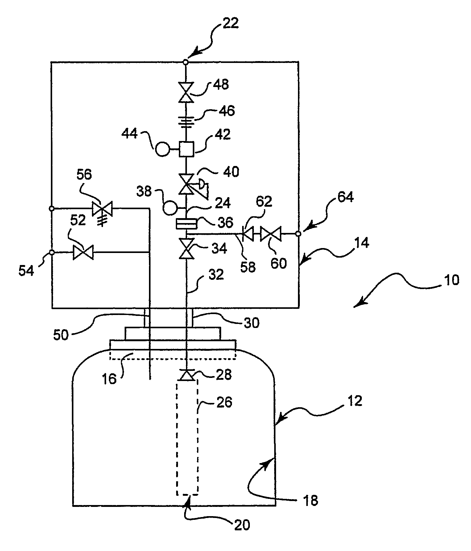
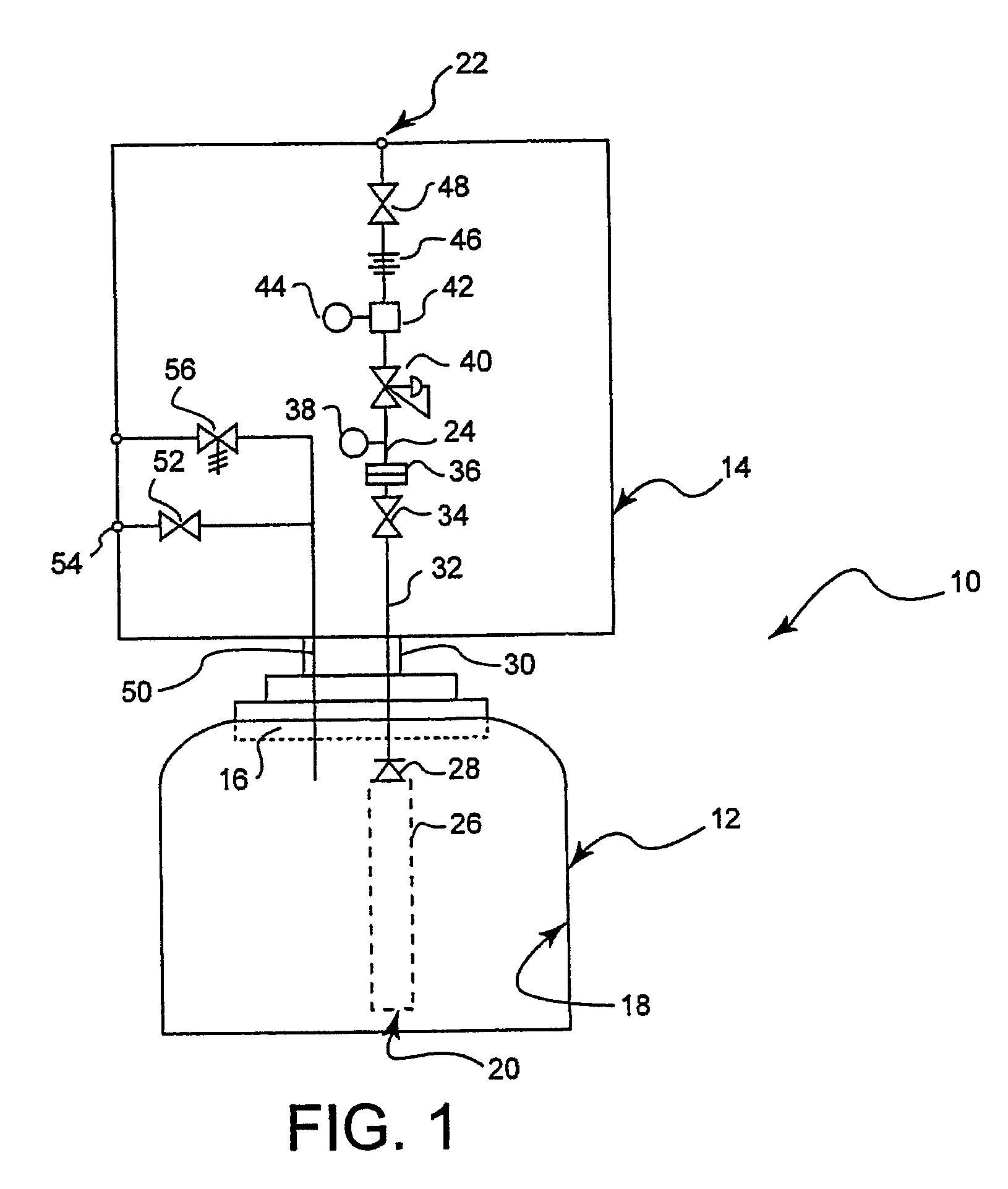
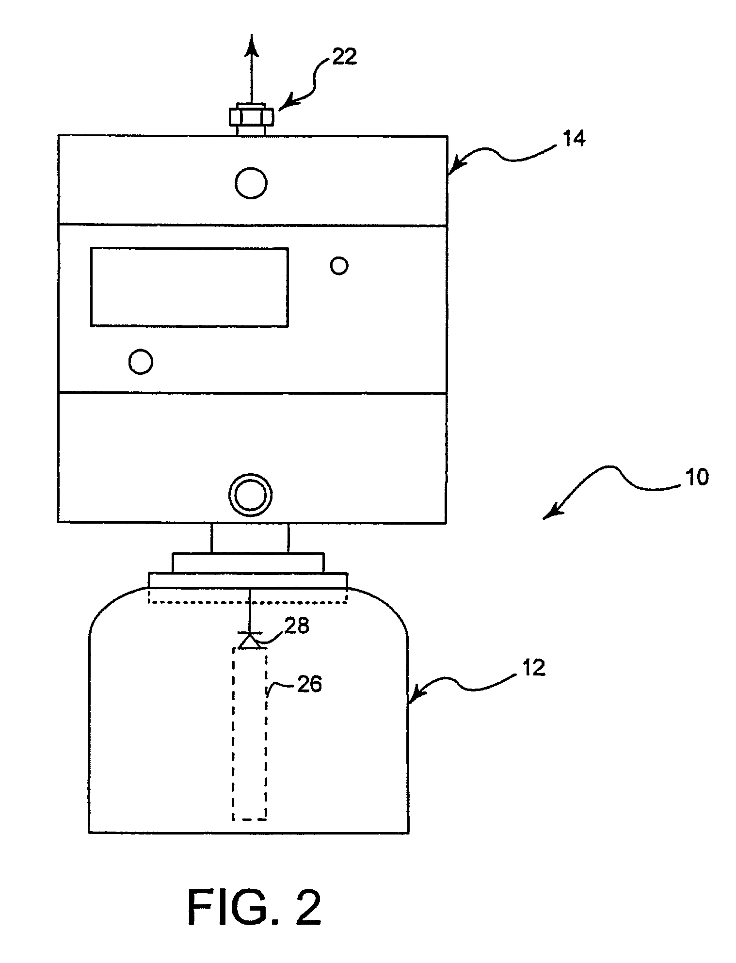
[0038]Referring now to the drawings, wherein like reference numbers refer to like elements throughout the several views, FIGS. 1 through 6 show several configurations of an assembly for containing and delivering hazardous fluids from a pressurized container. Because the common details are given the same reference numbers in each of the figures, their construction and operation will not be reiterated for each figure.

[0039]For the purposes of the present invention, the term “fluid” includes gases and liquids. The term “gas” encompasses both a permanent gas and a vapor of a liquefied gas. Unless otherwise indicated, all pressures discussed will be absolute pressures.

[0040]Permanent gases are gases that cannot be liquefied by pressure alone at ambient temperature, and for example can be supplied in fluid containers at pressures up to 300 bar gage. Examples are argon and nitrogen.

[0041]Fluids that liquefy under pressure as they are compressed for filling into a fluid container are not pe...


PUM

PropertyMeasurementUnit
pressuresaaaaaaaaaa
pressuresaaaaaaaaaa
pressuresaaaaaaaaaa

Abstract

A fluid control and gas delivery assembly and method for containing, receiving and storing hazardous fluids and for dispensing gas comprising a container, a fluid fill path, a gas dispensing path, a first shut-off valve, a pressure reducer, a fluid flow restrictor, a second shut-off valve and a fluid outlet connector. The first shut-off valve is positioned in said gas dispensing path upstream of a pressure reducer. A fluid flow restrictor downstream of the pressure reducer has a fluid flow restriction path configured to restrict the flow of the fluid delivered to the fluid flow restrictor at the delivery pressure to a maximum mass flow rate that is equal to or less than the allowable mass flow rate standard for the hazardous fluid. The second shut-off valve is positioned in said gas dispensing path downstream of said pressure reducer.

Description

CROSS-REFERENCE TO RELATED APPLICATIONS[0001]Not presently applicable.STATEMENT REGARDING FEDERALLY SPONSORED RESEARCH OR DEVELOPMENT[0002]Not applicable.REFERENCE TO A SEQUENCE LISTING, A TABLE, OR A COMPUTER PROGRAM LISTING SUBMITTED ON A COMPACT DISK[0003]Not applicable.FIELD OF THE INVENTION[0004]The present invention generally relates to a fluid control and gas delivery assembly for containing, receiving and storing fluids and for dispensing gas from a fluid container, vessel or tank (“fluid container”). In particular, the present invention employs a fluid control and gas delivery assembly having an integrated fluid flow restrictor. The present invention further relates to a method of control and delivery of fluid from such a fluid control and gas delivery assembly.BACKGROUND OF THE INVENTION[0005]Control and delivery of high purity corrosive, toxic, oxidant, inert, pyrophoric fluids and mixtures of such fluids from fluid containers is necessary to a wide range of processing an...

Claims


Application Information

Patent Timeline
Patent Type & Authority Patents(United States)
IPC IPC(8): B65B1/30F17C9/00F17C13/00F17C7/00F17C13/04
CPCF17C13/04F17C2205/0338F17C2205/035F17C2205/0391F17C2227/044F17C2227/048F17C2270/0518Y10T137/87249
Inventor HERTZLER, BENJAMIN LEESHAY, ROBERT HARRISONBOTELHO, ALEXANDRE DE ALMEIDA
Owner AIR PROD & CHEM INC
Why Eureka
Try Eureka