
Disconnect devices

a technology of disconnect devices and connectors, applied in the direction of hose connections, borehole/well accessories, couplings, etc., can solve the problems of lack of torsional capacity, obstructive castellations provided on the body associated with the lower sub-b>3/b>, and interference with attempts, so as to facilitate the makeup of the connection, reduce wear, and contribute to the strength and integrity of the connection

Inactive Publication Date: 2006-12-26
WEATHERFORD TECH HLDG LLC
View PDF42 Cites 34 Cited by
  • Summary
  • Abstract
  • Description
  • Claims
  • Application Information

AI Technical Summary

Benefits of technology

[0011]Preferably the at least one protrusion is substantially convex and the at least one correspondingly shaped depression or hole is concave. The at least one depression or hole is concave and the at least one protrusion is correspondingly convex, contributing to the strength and integrity of the connection formed between the depression or hole and protrusion axially and rotationally, while facilitating makeup of the connection and limiting wear.

Problems solved by technology

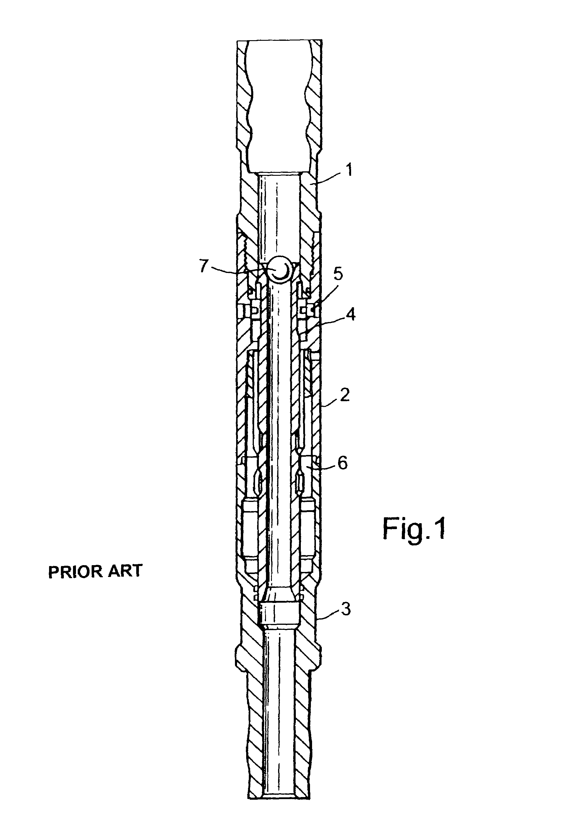
However, the castellations provided on the body associated with the lower sub 3 can be obstructive and interfere with the attempts to fish out the bottom hole assembly.
As with the collet system, however, because they have a turned, 360° circumferential, profile they lack any torsional capacity and are accordingly provided with keying castellations.
As with the collet-based device, these castellations can interfere with fishing operations.

Method used


Image

  • Disconnect devices
  • Disconnect devices
  • Disconnect devices

Examples


Embodiment Construction

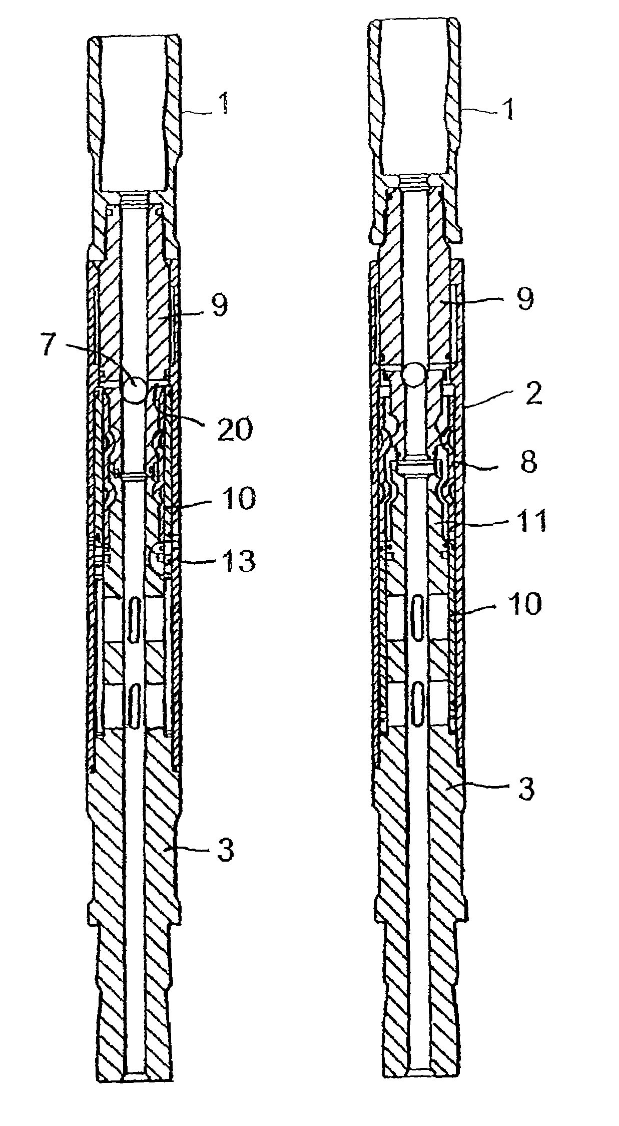
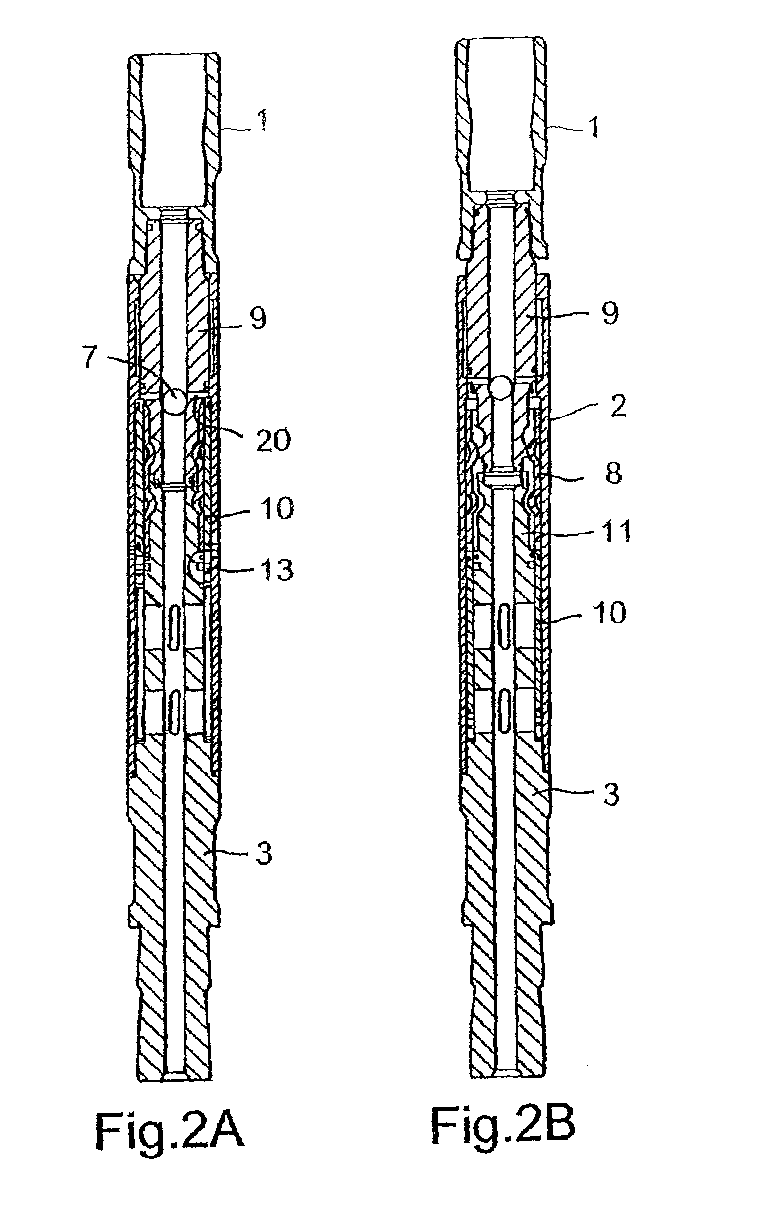
[0028]Referring to FIGS. 2 to 8, the preferred embodiment of disconnect tool has an overall configuration that is similar to that of the prior art disconnect tool of FIG. 1 in having a top sub 1, intermediate sub / tubular disconnect body 2 and lower / bottom sub 3. The device of the present invention also has a tubular coupling component that extends within the bore of the intermediate sub / disconnect body 2 and which is releasably coupled to the lower sub 3. The disconnect tool / device of the present invention, however, has no collet but instead has a slip assembly 8, the upper in use end of which cooperatively engages with a lower in use end of a tubular coupling component, or mandrel, 9 threaded to the top sub 1. The lower in use end of the slip assembly 8 couples with an upper in use end of a similar tubular component 11 extending upwardly from the lower sub 3. The tubular coupling component 11 of the lower sub 3 is formed integrally with the lower sub 3.

[0029]The slip assembly 8 is ...


PUM


Abstract

A disconnect device for use as part of a tubing string downhole in an oil or gas well and which comprises a tubular body, at least one slip held within the tubular body, and a sleeve housed within the tubular body to hold the at least one slip in coupling engagement with at least one of a coupling component of an upper sub and a coupling component of a lower sub, in use, the sleeve being selectively moveable relative to the at least one slip to release the slip and thereby release the coupling, wherein the slip cooperatively engages with at least one of the coupling component of the upper sub and the coupling component of the lower sub by means of at least one localized protrusion on the slip or on the coupling component extending into a corresponding shaped local depression or hole in the other of the at least one slip and the coupling component whereby tensile load and torque may be transmitted by the coupling, that part of the device which is to be released and left downhole by releasing the coupling engagement having a fishneck configuration to enable subsequent retrieval by a fishing tool.

Description

CROSS-REFERENCE TO RELATED APPLICATIONS[0001]This application is the National Stage of International Application No. PCT / GB01 / 05233, filed on Nov. 27, 2001, and published under PCT Article 21(2) in English, and claims priority of Great Britain Application No. 0029097.3, filed on Nov. 29, 2000. The aforementioned related patent applications are herein incorporated by reference in their entirety.BACKGROUND OF THE INVENTION[0002]1. Field of the Invention[0003]The present invention relates to disconnect devices—releasable connectors—that are used downhole in oil or gas wells. The invention is particularly, though not necessarily exclusively, relevant to hydraulic disconnects as are used in coiled tubing workstrings to release the bottom hole assembly of the workstring in a controlled fashion.[0004]2. Description of the Related Art[0005]Hydraulic disconnect devices have been in use for many years and usually work along the following basis. Referring to FIG. 1 of the accompanying drawings...

Claims


Application Information

Patent Timeline
Patent Type & Authority Patents(United States)
IPC IPC(8): E21B17/02E21B17/06E21B23/04
CPCE21B17/06E21B23/04E21B23/0413
Inventor BOWLES, RODNEY GORDON
Owner WEATHERFORD TECH HLDG LLC
Learn More