Stacked laminate CMC turbine vane

a technology of turbine vane and laminate, which is applied in the direction of machines/engines, liquid fuel engines, natural mineral layered products, etc., can solve the problems of low interlaminar tensile and shear strength of cmc materials, preventing the viability of these concepts, and delamination of cmc materials, etc., to achieve enhanced cooling and structural features

Active Publication Date: 2006-12-26
SIEMENS ENERGY INC
View PDF47 Cites 100 Cited by
  • Summary
  • Abstract
  • Description
  • Claims
  • Application Information

AI Technical Summary

Benefits of technology

[0008]Thus, there is a need for a vane that can address the problems encountered in prior CMC airfoil design and construction. Specifically, there is a need for a stacked CMC laminate vane that aligns the reinforcing fibers in the anticipated direction of high thermal stresses, thereby pitting strength against stress. Ideally, the construction can allow for the inclusion of enhanced cooling and structural features.
[0017]The plurality of laminates can be held together in several ways. For instance, at least one pair of adjacent laminates can be joined by co-processing, sintering and / or by applying bonding material between the laminate pair. In another embodiment, a fastening system can be provided for holding the plurality of laminates in radial compression. In one embodiment, the fastening system can include an elongated fastener and a retainer. The fastener can extend through a radial opening provided in the vane. At least one end of the fastener can be closed by the retainer. In some embodiments, a stiffened fastening system may be desired, for example, to minimize concerns of radial creep of the fasteners and laminates. The stiffened fastening system can include at least two tie rods extending radially through one or more openings provided in the vane. The tie rods can be joined so as to form a single rigid fastener. The ends of the tie rods can be closed by retainers so as to hold the plurality of laminates in radial compression.
[0018]The laminates can be shaped or stacked to form an irregular outer peripheral surface of the vane. For example, the plurality of laminates can include alternating large laminates and small laminates so as to form a vane having a stepped outer peripheral surface. One or more laminates can be staggered from the other laminates to form an irregular outer peripheral surface. In another embodiment, at least two of the laminates in the stack can have a tapered outer peripheral edge. In such case, the two laminates can be stacked such that the tapered edge of each laminate can extend in substantially the same direction or in substantially opposite directions. Yet another manner of forming a vane with an irregular outer peripheral surface is by providing at least one laminate with recesses, serrations, and / or cutouts about at least a portion of the outer peripheral surface of the laminate. A thermal insulating material can be applied over the outer peripheral surface of the vane. Any of the above irregular outer peripheral surfaces can, among other things, facilitate bonding of a thermal insulating material over the stepped outer peripheral surface of the vane.

Problems solved by technology

However, precise and costly machining of individual laminates preclude the viability of these concepts.
While providing some advantages over monolithic ceramics, the use of CMC materials in airfoil design introduce a new set of challenges.
For example, CMC materials suffer from their low interlaminar tensile and shear strengths, which present special challenges in situations where an internally cooled component, such as a turbine vane, experiences large through thickness thermal gradients and the resultant high thermal stresses.
In the above-described CMC airfoil construction, high thermal gradients cause high interlaminar tension (i.e. high stresses) in the weakest direction of the CMC material, resulting in delamination of the CMC.
However, these approaches carry numerous development and manufacturing disadvantages and performance penalties.
Further, prior CMC airfoil constructions pose various manufacturing challenges.
For instance, current oxide CMCs exhibit anisotropic shrinkage during curing, resulting in interlaminar stress buildup for constrained geometry shapes.
Further complicating matters is that non-destructive evaluation methods to discover interlaminar defects are difficult on large, complex shapes such as gas turbine vanes.
In addition, dimensional control is unproven for complex shapes and may be difficult to achieve in close-toleranced parts such as airfoils.
Further, achievement of target material properties in large and / or complex shapes has proved to be difficult.
There are also scale-ability limitations as current processes are labor-intensive, requiring very skilled technicians to carefully hand lay-up each reinforcing layer.
Consequently, the trailing edge is only weakly held together and is vulnerable to the pressure of the cooling air in the trailing edge exit holes.

Method used


Image

  • Stacked laminate CMC turbine vane
  • Stacked laminate CMC turbine vane
  • Stacked laminate CMC turbine vane

Examples


Embodiment Construction

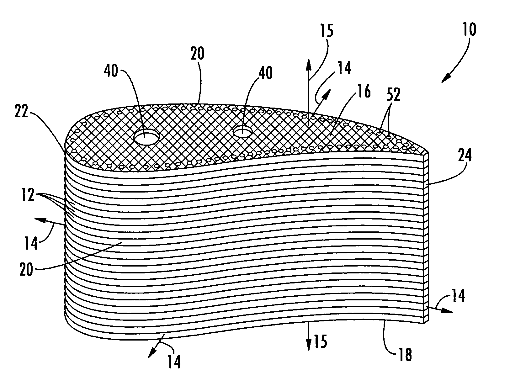
[0038]Embodiments of the present invention address the shortcomings of earlier stacked laminate vane designs by providing a robust vane that makes use of the anisotropic strength orientations of ceramic matrix composite (CMC) materials such that the high stresses inherent in a cooled vane are aligned with the strongest material direction, while the stresses in the weakest material direction are minimized. Embodiments of the invention will be explained in the context of one possible turbine vane, but the detailed description is intended only as exemplary. Embodiments of the invention are shown in FIGS. 1–16, but the present invention is not limited to the illustrated structure or application.

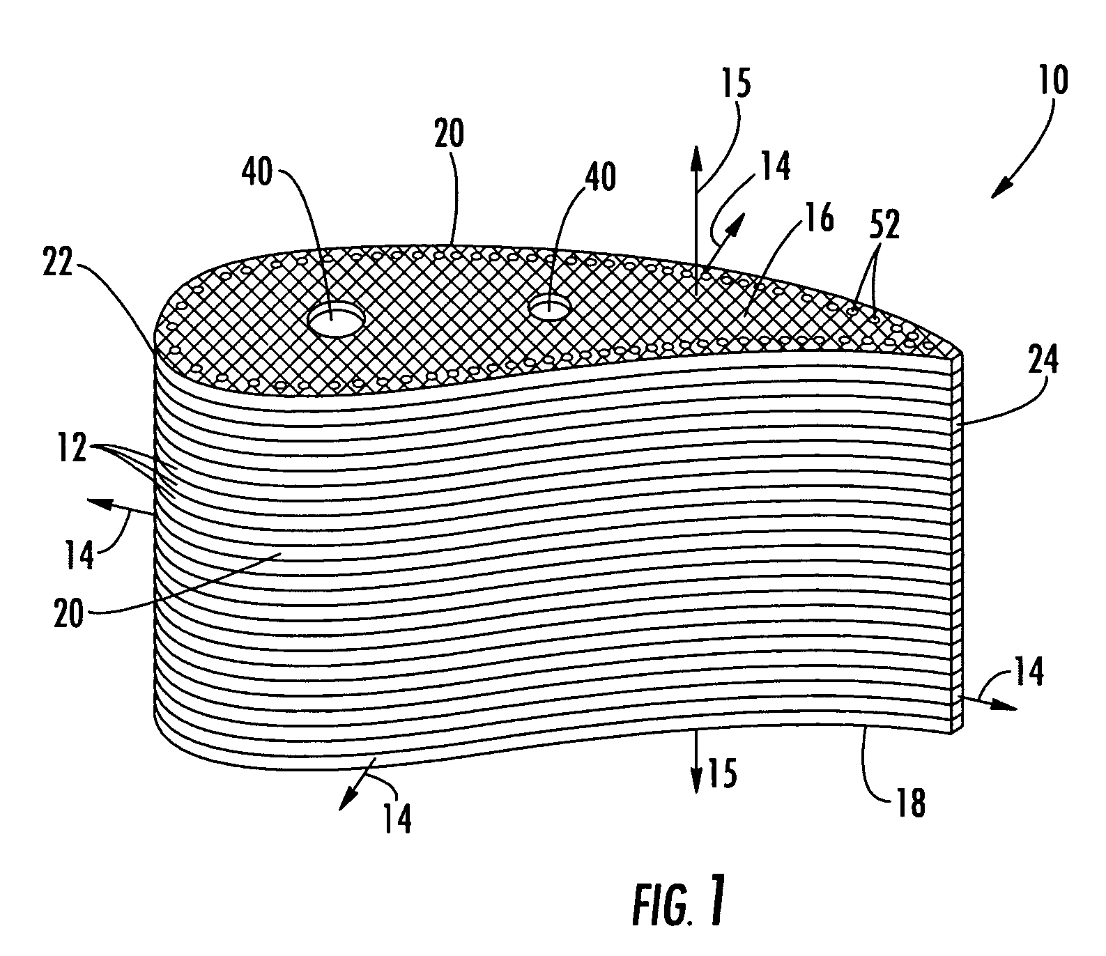
[0039]FIG. 1 shows one possible construction of a turbine vane assembly 10 according to aspects of the invention. The vane 10 can be made of a plurality of CMC laminates 12. The vane 10 can have a radially outer end 16 and a radially inner end 18 and an outer peripheral surface 20. The term “radi...


PUM

PropertyMeasurementUnit
tensile strengthaaaaaaaaaa
compressive strengthaaaaaaaaaa

Abstract

Embodiments of the invention relate to a robust turbine vane made of stacked airfoil-shaped CMC laminates. Each laminate has an in-plane direction and a through thickness direction substantially normal to the in-plane direction. The laminates have anisotropic strength characteristics in which the in-plane tensile strength is substantially greater than the through thickness tensile strength. Thus, the laminates can provide strength in the direction of high thermal gradients and, thus, withstand the associated high thermal stresses. The laminates are relatively weak in through thickness (interlaminar) tension, but, in operation, relatively low through thickness tensile stresses can be expected. The laminates can be strong in through thickness compression; accordingly, the laminate stack can be held in through thickness compression by one or more fasteners. The CMC material can permit the inclusion of additional features such as cooling passages, ribs, spars, and thermal coatings, without compromising the strength characteristics of the material.

Description

FIELD OF THE INVENTION[0001]The invention relates in general to turbine engines and, more specifically, to stationary airfoils in a turbine engine.BACKGROUND OF THE INVENTION[0002]A variety of materials and construction methods have been used in connection with turbine airfoils. For example, laminated airfoil concepts are known that use monolithic ceramic materials. Reasons for using such constructions include the reduction of impact stresses, reduction of thermally induced stresses from differential cooldown rates (e.g., thin trailing edge sections versus thicker sections), and accommodation of attachment to metals. However, precise and costly machining of individual laminates preclude the viability of these concepts.[0003]Another type of material used in connection with turbine airfoils is ceramic matrix composites (CMC). CMC includes a ceramic matrix reinforced with ceramic fibers. In one CMC airfoil construction, fabric layers are wrapped over each other so that the fibers are p...

Claims


Application Information

Patent Timeline
Patent Type & Authority Patents(United States)
IPC IPC(8): F01D9/00
CPCF01D5/147F04D29/388F05D2230/23F05D2300/601F05D2300/603F05D2300/614Y10T428/249928Y10T428/249929
Inventor THOMPSON, DANIEL G.VANCE, STEVEN JAMESMORRISON, JAY A.
Owner SIEMENS ENERGY INC
Why Eureka
Try Eureka