Downflow catalytic cracking reactor and its application

Active Publication Date: 2006-12-26
CHINA PETROCHEMICAL CORP +1
View PDF26 Cites 10 Cited by
  • Summary
  • Abstract
  • Description
  • Claims
  • Application Information

AI Technical Summary

Benefits of technology

[0012]One object of the present invention is to provide a downflow catalytic cracking reactor w

Problems solved by technology

In a riser reactor, the hydrocarbon oil feedstock is hard to fully atomize and vaporize in time when sprayed into the dense catalyst bed at the bottom of the riser through the nozzle.
Meanwhile, there exists rather severe backmixing since the catalyst flows against the direction of gravity in the riser.
In such a reaction environment, more dry gas and coke are also produced when most of the heavy oil is cracked, which will reduce the yield of the products with higher added values such as light oil and LPG.
The conversion of heavy oils in this kind of downflow pipe reactor is rather low because the concentration of the catalyst is quite low when the hydrocarbon feed initially contacts the catalyst and thereby the oil/catalyst contact efficiency is not ideal.
Although this downflow reactor has strengthened the mixing between the feed oil and the catalyst through the cross-flow contact, the conversion of the heavy oil is not sufficient because the hydrocarbon oil feed still contacts the free-falling catalyst, the concentration of the catalyst in this reactor is still low, and the quantity of the active center which can contact feed oil effectively is very limited.
Although this process raises the concentration of the catalyst in the initial catalyst/oil contact section to a certain extent by increasing the catalyst/oil ratio, the

Method used


Image

  • Downflow catalytic cracking reactor and its application
  • Downflow catalytic cracking reactor and its application
  • Downflow catalytic cracking reactor and its application

Examples


example 1

[0045]The present example demonstrates that the product distribution and the properties of the products have been markedly improved by using the downflow reactor provided by the present invention when conducting the catalytic cracking reaction under the conventional catalytic cracking conditions

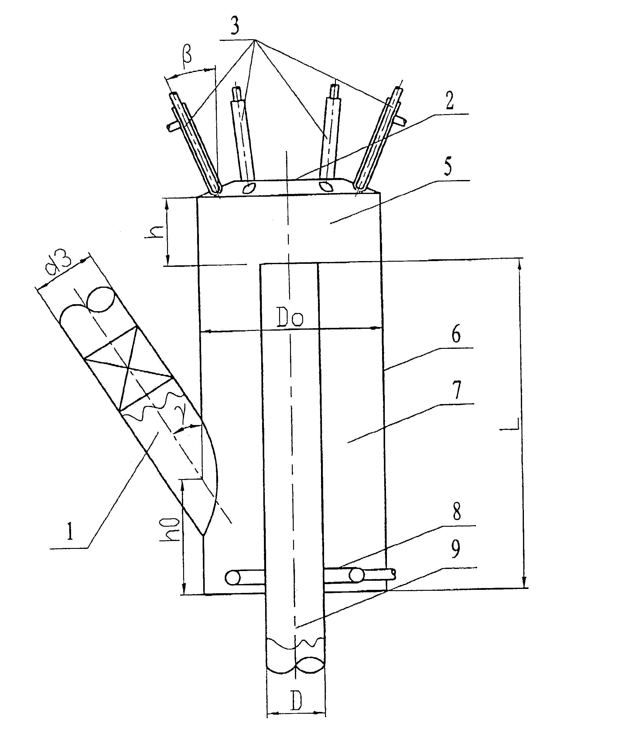
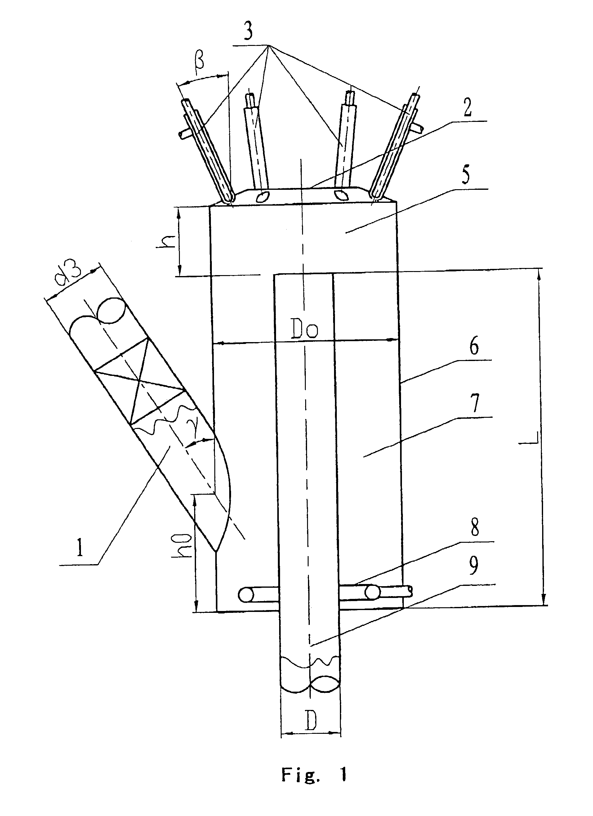
[0046]The principle flow diagram of the catalytic cracking pilot plant used in the experiment is shown in FIG. 12 and the schematic diagram of the structure of the downflow reactor is shown in FIG. 1. Diameter of the downflow reaction pipe D=20 mm; diameter of the reactor vessel Do=2.5D; height difference from the inlet of the downflow pipe to the bottom of the reactor vessel L=6D; the number of the nozzles was 4; the angle of each nozzle to the vertical direction β=30° and height difference from the outlet of the nozzle to the inlet of the downflow pipe h=1.25D; diameter of the catalyst delivery pipe d3=0.8D, the angle of the central line of the catalyst delivery pipe to the vertical directi...

example 2

[0049]The present example demonstrates that the distribution and properties of the product have been markedly improved by using the downflow reactor provided by the present invention.

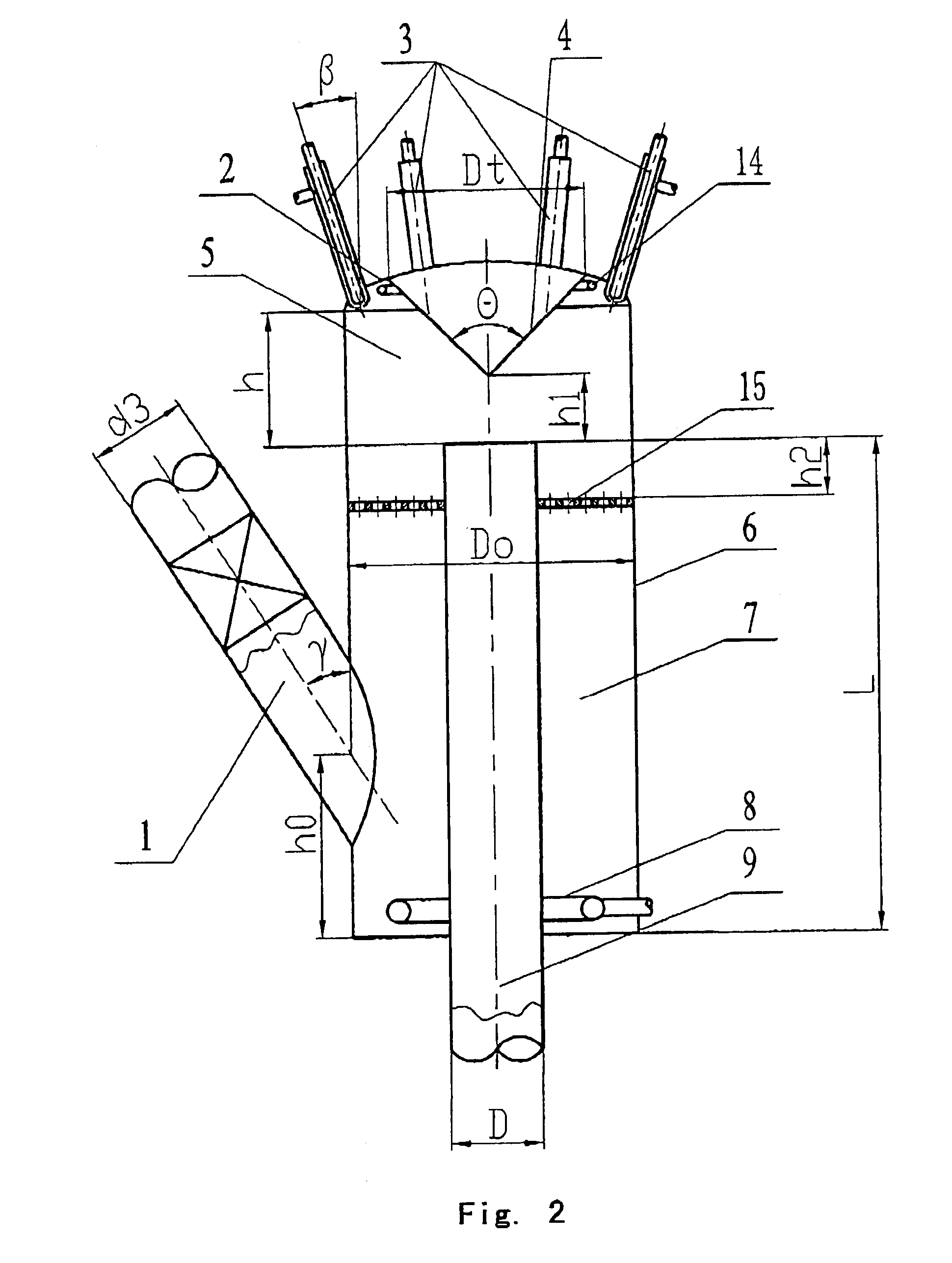
[0050]The principle flow diagram of the catalytic cracking pilot plant used in the experiments is shown in FIG. 13 and the schematic diagram of the structure of the downflow reactor is shown in FIG. 10. Diameter of the downflow reaction pipe D=20 mm; cone angle of the reactor vessel β0=22.5°, and diameter of the bottom rim of the reactor vessel Db=2D; height difference from the upper rim of the diameter reduced section of the downflow pipe's inlet structure to the bottom of the reactor vessel L=6D; the number of the nozzles was 6; the angle of each nozzle to the vertical direction β=45° and height difference from the outlet of the nozzle to the upper rim of the diameter reduced section of the downflow pipe h=1.35D; diameter of the bottom of the guide cone Dt=3D, its cone angle Θ=100°, and height differe...

example 3

[0053]The present example demonstrates the experimental results derived under rather rigorous conditions by using the downflow reactor provided by the present invention.

[0054]The structure of the downflow reactor used in the present example is shown in FIG. 11. Diameter of the downflow reaction pipe D=20 mm; diameter of the lower end of the lower cone section of reactor vessel 6 of the catalyst lifting zone Db=2.5D, diameter of the upper end Do=3.5D, and its height was 3D; height of the upper cylinder h8=2D; height difference from the inlet of the downflow pipe to the bottom of reactor vessel 6 L=5D; height difference from the outlet of nozzle 3 to the inlet of downflow pipe 9 h=1.5D; catalyst delivery pipe 1 was two symmetrically arranged inclined pipes with diameter d3=0.7D, the angle of their central lines to the vertical direction γ=30°, and height difference from the crossing point of the catalyst delivery pipe's central line with the reactor vessel to the bottom of the reactor...


PUM

PropertyMeasurementUnit
Electric dipole momentaaaaaaaaaa
Temperatureaaaaaaaaaa

Abstract

A downflow catalytic cracking reactor, comprising the following components: catalyst delivery pipe (1), reactor top cover (2), feed nozzle (3), reactor vessel (6), downflow reaction pipe (9), the upper end of the outer body is close connected to top cover (2) along the direction of circumference; the bottom of the outer wall body is close connected to the outer wall of the downflow reaction pipe; the upper section of the downflow reaction pipe is located inside the reaction vessel, while the lower section extends from the bottom of the outer body; feed nozzle (3) is located on the top cover (2) and/or side wall of the reactor vessel (6) with the outlet of the feed nozzle being above the inlet of the downflow reaction pipe; catalyst delivery pipe (1) is fixedly joined to the reactor vessel and in communication with catalyst lifting zone (7) formed by the reaction vessel and the downflow reaction pipe.

Description

FIELD OF THE INVENTION[0001]The present invention relates to a reactor for the catalytic cracking of petroleum hydrocarbons in the absence of hydrogen, in particular, it relates to a downflow catalytic cracking reactor and its application.DESCRIPTION OF THE PRIOR ART[0002]Along with the development of economy, the demand in the whole world for vehicle fuels and light olefins is continually increasing. The development of deep processing of heavy oils for increasing the supply of light oils and light olefins will be a significant developing strategy of the refinery industry in 21st century. Catalytic cracking process has the advantages of wide adaptability to the feedstock, high conversion depth of heavy oil, and high olefin content in the produced LPG, therefore it is the most important technology for the secondary processing of heavy oils. The catalytic cracking units are large in scale, and needs less investment, so they are the support for the economic benefit of all refineries in...

Claims


Application Information

Patent Timeline
IPC IPC(8): B01J8/18B32B27/04C10G11/18B01J8/12B01J8/00B01J8/22B01J8/26C07B37/06C07B61/00C07C4/06C07C11/04C07C11/06C10G11/05C10G11/14C10G11/16
CPCB01J8/002B01J8/0045B01J8/008B01J8/22B01J8/26C10G11/14C10G11/16C10G11/18
Inventor XU, KEJIAHOU, SHUANDILONG, JUNZHONG, XIAOXIANGZHANG, JIUSHUNZHANG, ZHANZHULI, SONGNIANWU, XUEFENGHE, JUN
Owner CHINA PETROCHEMICAL CORP
Why Eureka
Try Eureka