Mask handling method, and mask and device or apparatus comprising a gripper therefor, device manufacturing method and device manufactured thereby

Inactive Publication Date: 2006-12-26
ASML NETHERLANDS BV
View PDF9 Cites 15 Cited by
  • Summary
  • Abstract
  • Description
  • Claims
  • Application Information

AI Technical Summary

Benefits of technology

[0016]One embodiment of the present invention includes a method of handling a reflective mask suitable for patterning a projection beam of extreme ultraviolet electromagnetic radiation in a lithographic projection apparatus, wherein said method comprises kinematically-determined holding said mask while handling, said kinematically-determined holding comprising cooperation of a set of protrusions provided on a gripper with a respective set of recesses provided in a circumferential region of the mask. Handling the mask in such a manner both provides for a delicate gripping t

Problems solved by technology

Further, it presents a very simple and uncomplicated way of holding the mask, not requiring any need for sensors to determine p

Method used


Image

  • Mask handling method, and mask and device or apparatus comprising a gripper therefor, device manufacturing method and device manufactured thereby
  • Mask handling method, and mask and device or apparatus comprising a gripper therefor, device manufacturing method and device manufactured thereby
  • Mask handling method, and mask and device or apparatus comprising a gripper therefor, device manufacturing method and device manufactured thereby

Examples


Embodiment Construction

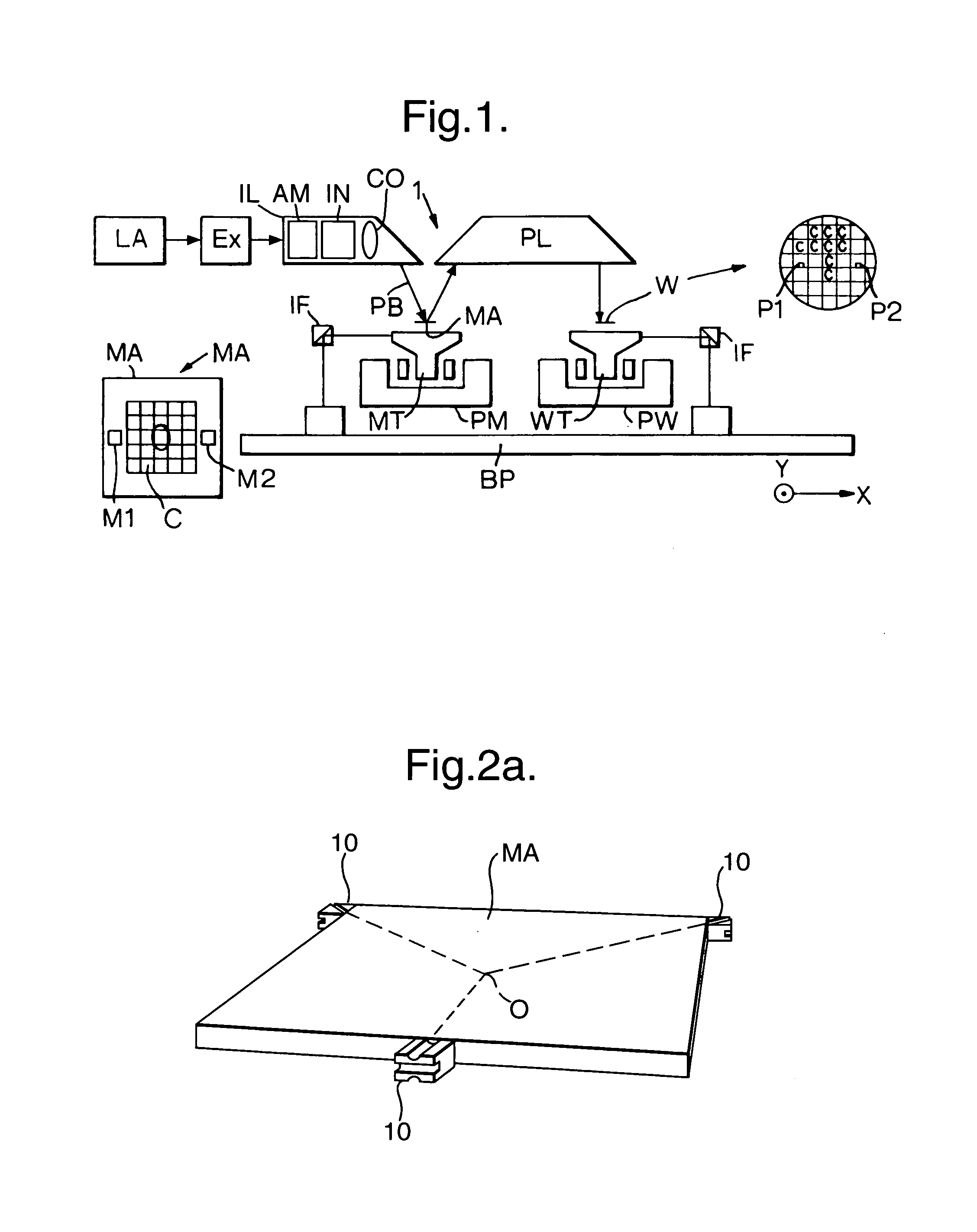
[0043]FIG. 1 schematically depicts a lithographic projection apparatus 1 according to embodiments of the present invention. The apparatus comprises:

[0044]a radiation system LA, IL for supplying a projection beam PB of EUV radiation;

[0045]a first object table (mask table) MT for holding a mask MA (e.g. a reticle), and connected to first positioning apparatus PM for accurately positioning the mask with respect to item PL;

[0046]a second object table (substrate table) WT for holding a substrate W (e.g.a resist-coated silicon wafer), and connected to second positioning apparatus PW for accurately positioning the substrate with respect to item PL;

[0047]a projection system (“lens”) PL for imaging an irradiated portion of the mask MA onto a target portion C (die) of the substrate W. As here depicted, the projection system is of a reflective type, examples of which are, for instance, disclosed in European patent application EP 01309353.9, incorporated herein by reference.

[0048]The source LA ...


PUM


Abstract

A mask for use in a lithographic projection apparatus comprises three brackets arranged on the circumference of the mask. The brackets are provided with grooves directed to a common imaginary point and are intend to cooperate with three pins provided on a mask gripper present in a mask handling apparatus or device. Preferably, the pins are provided with a rounded top for insertion in associated grooves of the brackets to provide a kinematically-determined mechanical position of the mask on the gripper.

Description

BACKGROUND OF THE INVENTION[0001]This application claims priority from EP01301864.3 filed Mar. 1, 2001, herein incorporated by reference.[0002]1. Field of the Invention[0003]The present invention relates generally to lithographic apparatus and more particularly to lithographic apparatus using reflective masks.[0004]2. Background of the Related Art[0005]In general, a lithographic extreme ultraviolet radiation lithographic apparatus include, a reflective mask, a gripper to hold the mask, a radiation system for providing the projection beam of extreme ultraviolet electromagnetic radiation, a mask table for holding the reflective mask, the mask serving to pattern the projection beam according to a desired pattern upon reflection of the projection beam at the mask so as to yield a patterned projection beam, a substrate table for holding a substrate and a projection system for projecting the patterned projection beam onto a target portion of the substrate.[0006]Lithographic projection app...

Claims


Application Information

Patent Timeline
IPC IPC(8): G01F9/00G03B27/58B65G49/00G03F7/20H01L21/027H01L21/673H01L21/68H01L21/683
CPCG03F7/707G03F7/70741H01L21/027
Inventor HEERENS, GART-JANHAM, ERIK LEONARDUSVAN DE VEN, BASTIAAN LAMBERTUS WILHEMUS MARINUS
Owner ASML NETHERLANDS BV
Why Eureka
Try Eureka