Catalyst temperature control on an electrically throttled engine

a technology of internal combustion engine and temperature control, which is applied in the direction of electric control, machines/engines, mechanical equipment, etc., can solve the problems of increasing engine fuel consumption, reducing long-term catalyst efficiency, and introducing drivability concerns

Active Publication Date: 2007-01-02
FORD GLOBAL TECH LLC
View PDF13 Cites 7 Cited by
  • Summary
  • Abstract
  • Description
  • Claims
  • Application Information

AI Technical Summary

Benefits of technology

[0006]One embodiment of the present invention includes a method to regulate catalyst temperature and engine torque. The method comprises: selecting a target catalyst temperature; comparing said target catalyst temperature to catalyst temperature; adjusting engine air amount based on said comparison temperature; and adjusting injected fuel amount based on said engine air amount. The method can be used to reduce the above-mentioned limitations of the prior art approaches.

Problems solved by technology

If sufficient temperatures reach emission-reducing catalysts for prolonged periods of time, reduction in long-term catalyst efficiency may result.
Since engine torque is not considered by the before-mentioned approach, the approach may introduce drivability concerns resulting from any torque variation.
Furthermore, the inventor has recognized that the approach increases engine fuel consumption while the catalyst temperature is being controlled by air-fuel enrichment.
While controlling catalyst temperature is important to protect a catalyst from deterioration, fuel consumption affects emissions and operating costs.

Method used


Image

  • Catalyst temperature control on an electrically throttled engine
  • Catalyst temperature control on an electrically throttled engine
  • Catalyst temperature control on an electrically throttled engine

Examples


Embodiment Construction

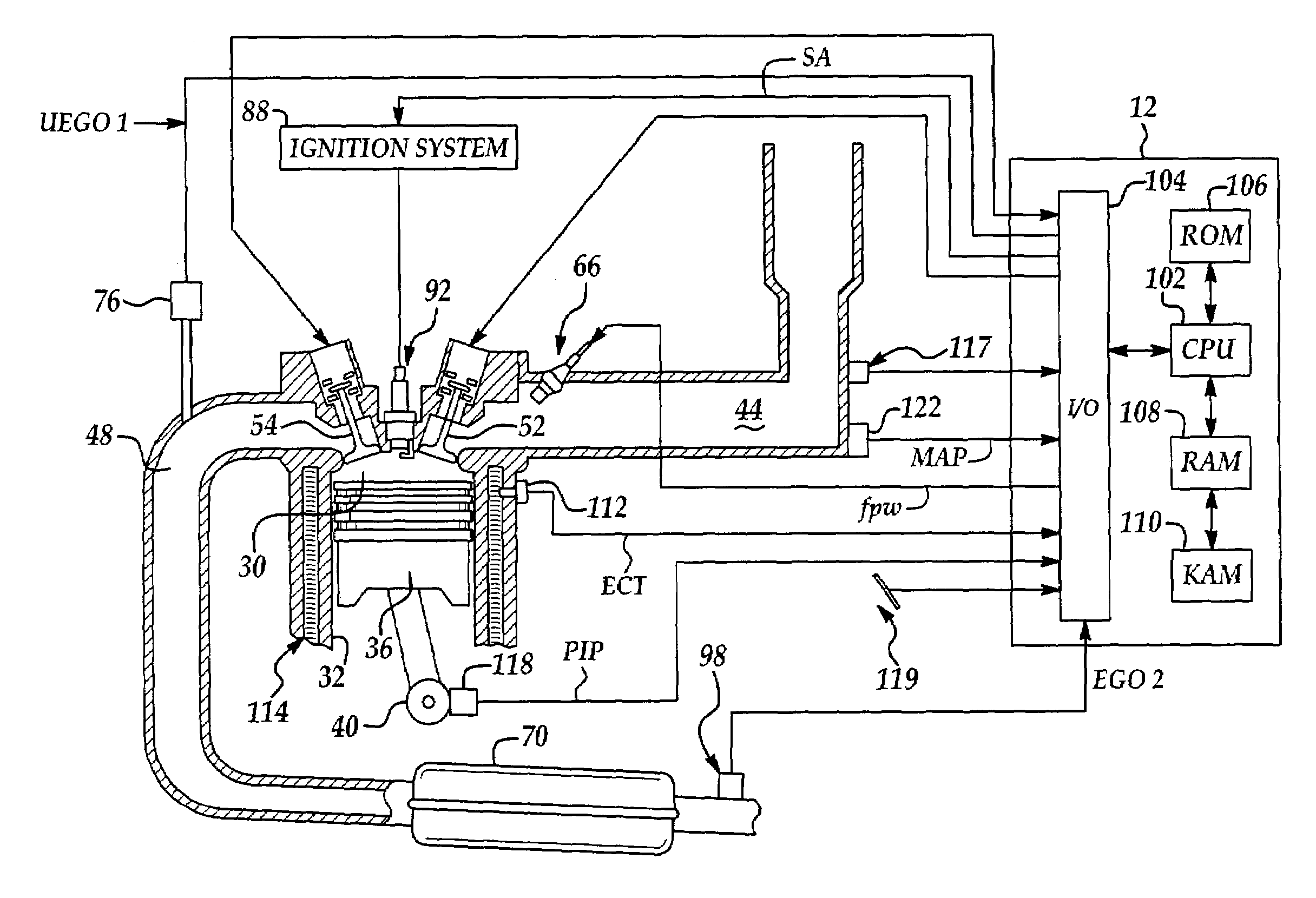
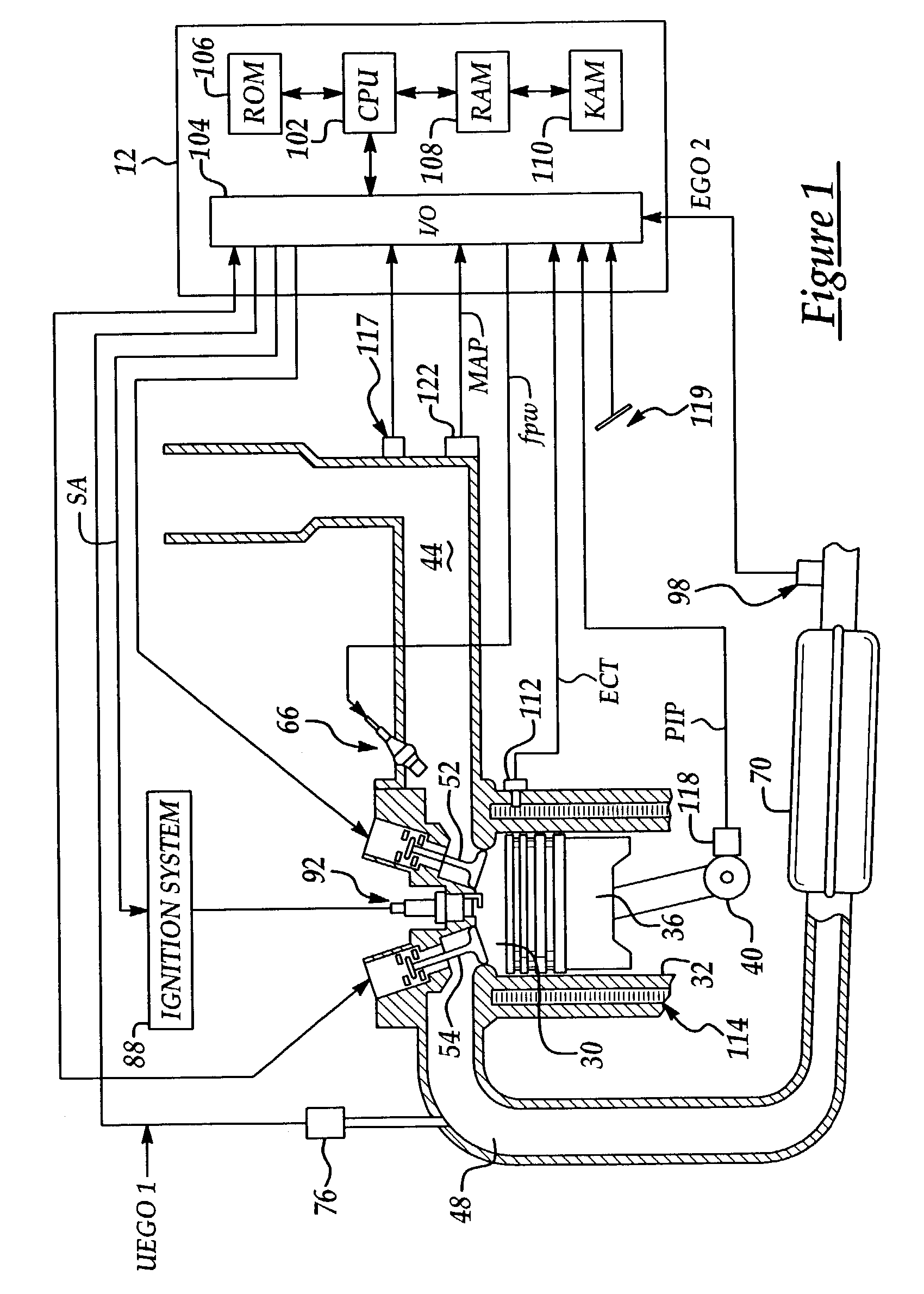
[0021]Referring to FIG. 1, internal combustion engine 10, comprising a plurality of cylinders, one cylinder of which is shown in FIG. 1, is controlled by electronic engine controller 12. Engine 10 includes combustion chamber 30 and cylinder walls 32 with piston 36 positioned therein and connected to crankshaft 40. Combustion chamber 30 is known communicating with intake manifold 44 and exhaust manifold 48 via respective intake valve 52 an exhaust valve 54. Intake manifold 44 is also shown having fuel injector 66 coupled thereto for delivering liquid fuel in proportion to the pulse width of signal FPW from controller 12. Fuel is delivered to fuel injector 66 by fuel system (not shown) including a fuel tank, fuel pump, and fuel rail (not shown). Alternatively, the engine may be configured such that the fuel is injected directly into the engine cylinder, which is known to those skilled in the art as direct injection.

[0022]Conventional distributorless ignition system 88 provides ignitio...


PUM


Abstract

A method to regulate catalyst temperature by adjusting engine air and fuel amounts. The method provides catalyst temperature regulation while reducing fuel consumption.

Description

FIELD OF INVENTION[0001]The present invention relates to a method for controlling an internal combustion engine and more particularly to a method for controlling catalyst temperature with an electrically throttled internal combustion engine.BACKGROUND OF THE INVENTION[0002]Certain driving conditions can produce elevated engine speed and load conditions that may increase engine exhaust feed-gas temperature. If sufficient temperatures reach emission-reducing catalysts for prolonged periods of time, reduction in long-term catalyst efficiency may result. Elevated catalyst temperatures can produce wash coat sintering and substrate deterioration, reducing wash coat surface area and catalyst efficiency. Catalyst temperature is commonly controlled using fuel enrichment because fuel enrichment reduces feed gas temperature without affecting catalyst long-term efficiency.[0003]One method to control catalyst temperature by adjusting fuel is described in U.S. Pat. No. 4,960,083. This method prov...

Claims


Application Information

Patent Timeline
Patent Type & Authority Patents(United States)
IPC IPC(8): F01N3/00F01N3/20F02D11/10F02D41/14
CPCF01N3/2006F01N3/2046F02D41/1446F02D41/1456F01N2430/06F01N2430/08F01N2430/10Y02T10/26F02D2041/001F02D2200/0802F02D2250/24F02D11/10Y02T10/12
Inventor MICHELINI, JOHN OTTAVIO
Owner FORD GLOBAL TECH LLC
Why Eureka
Try Eureka