Fuel conditioning assembly

a technology of fuel conditioning and assembly, which is applied in the direction of machine/engine, charge feed system, engine components, etc., can solve the problems of unburned or under-burned fuel, severe environmental problems, and natural inefficiency inherent in fuel combustion systems such as internal combustion engines, and achieves less maintenance, clean running, and increased fuel efficiency of vehicles.

Inactive Publication Date: 2007-01-02
ROYCE WALKER
View PDF28 Cites 15 Cited by
  • Summary
  • Abstract
  • Description
  • Claims
  • Application Information

AI Technical Summary

Benefits of technology

[0010]The fuel conditioning assembly is structured to chemically condition the fuel as it travels through the flow through passage. At least one preferred embodiment of the conditioning assembly of the present invention is structured to rearrange the molecular bonds of the fuel, such as through the generation of an electrostatic charge, with a catalytic effect that results in molecular repulsion which separates the fuel particles into a plurality of subatomic particles, thereby reducing the density of the fuel and substantially increasing a fuel burn efficiency. As used herein, the term subatomic particles is intended to describe the atomization of the fuel, which leads to turbulence and the subsequent formation of separated molecules of fuel with a lower vapor density resulting in better combustion. Further, the construction and resulting performance characteristics of at least one preferred embodiment of the present invention results in an “atomization” or dispersion of any of a variety of fuels which may be utilized when practicing the present invention. As set forth in greater detail herein the fuel may include, but not be limited to, gasoline, diesel, bio-diesel, etc. As a result of the aforementioned atomization or dispersion, the fuel is transformed into small droplets having a high surface area thereby lowering the fuel vapor density and increasing the completeness of fuel combustion.
[0019]An added object of the present invention is to provide a fuel conditioning assembly that provided beneficial effects in a variety of different types of combustion systems which use a variety of different fuels, by pre-conditioning the fuel prior to combustion.

Problems solved by technology

The natural inefficiency inherent in fuel combustion systems, such as internal combustion engines, is well documented.
Specifically, internal combustion engines utilizing fossil fuels and other combustion systems using a variety of different types of fuels and fuel mixtures typically emit unburned or under-burned fuel from the exhaust as well as the undesirable by-products of combustion.
This under-burning of fuel causes severe environmental problems as the resultant pollutants, some of which are thought to be cancer causing, are emitted directly into the atmosphere.
This causes those engine components to wear out sooner and require frequent maintenance and repairs which can lead to shortened total engine life.
Furthermore, the incomplete combustion of fuel within an engine substantially under-utilizes the energy capacity of the fuel.
Specifically, in addition to the environmental concerns due to pollution attributed to the under-utilization of the energy capacity of fuel, there are also resultant losses in economic efficiency due to higher fuel and maintenance expenses as well as a generally shorter engine life.
Of course, such a procedure can also raise the engine temperature and can prove quite hazardous.
Unfortunately, however, it can be difficult to obtain and consistently add those additives in an efficient manner.
Also, if the additives are not completely soluble in the fuel, they may be quite harmful to the engine.
Accordingly, none of these devices have actually been successfully and practically incorporated with a combustion engine in a simple, economical, and maintenance free manner.
Although some of these devices do improve the combustion properties of the fuel somewhat, those skilled in the art have not been successful in substantially increasing the combustion properties in a practical and effective manner.
In particular, such devices have been unable to effectuate a substantial improvement such as would be necessary to offset the price of purchase and installation of the device into existing engines.

Method used


Image

  • Fuel conditioning assembly
  • Fuel conditioning assembly
  • Fuel conditioning assembly

Examples


Embodiment Construction

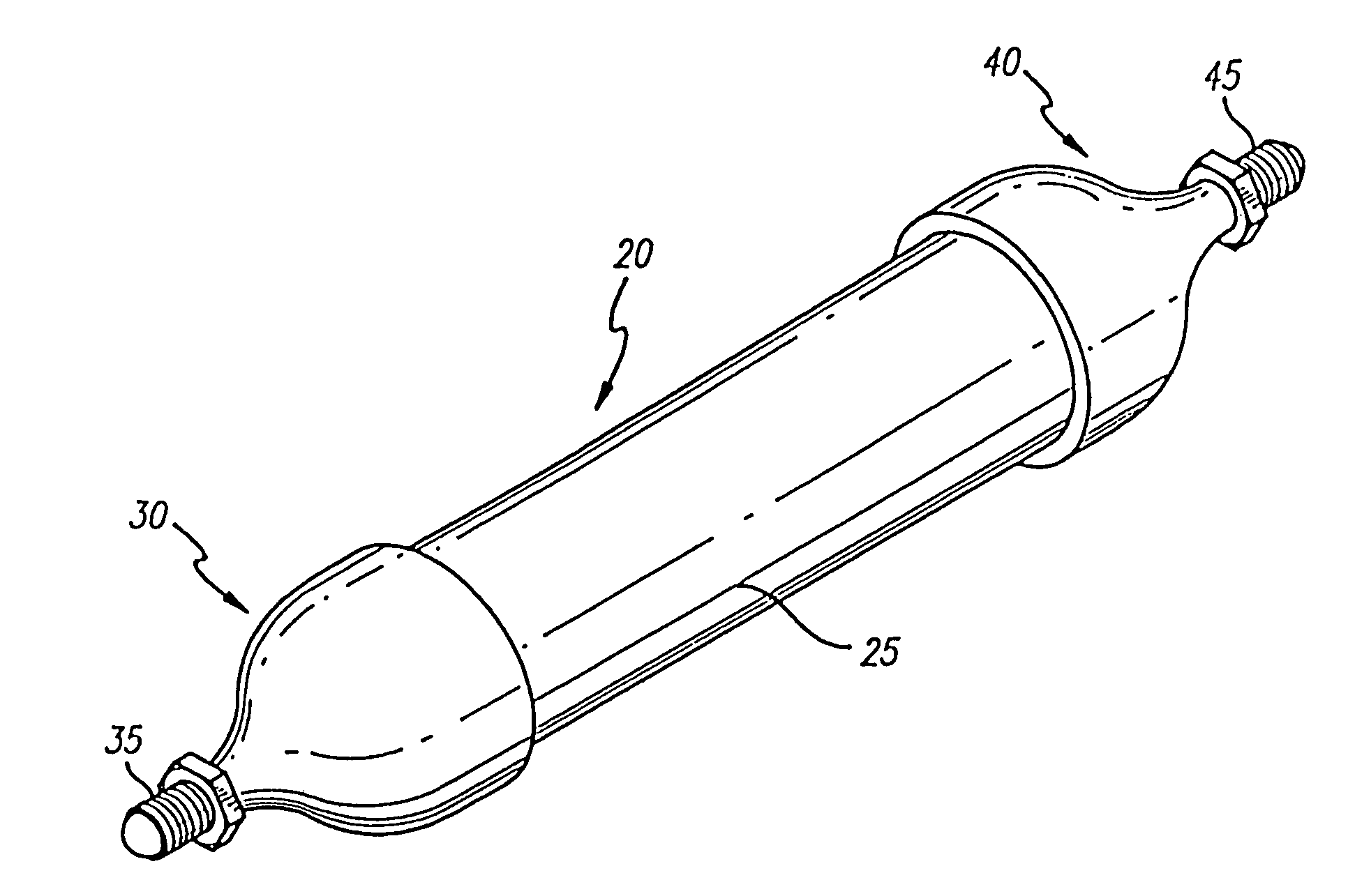
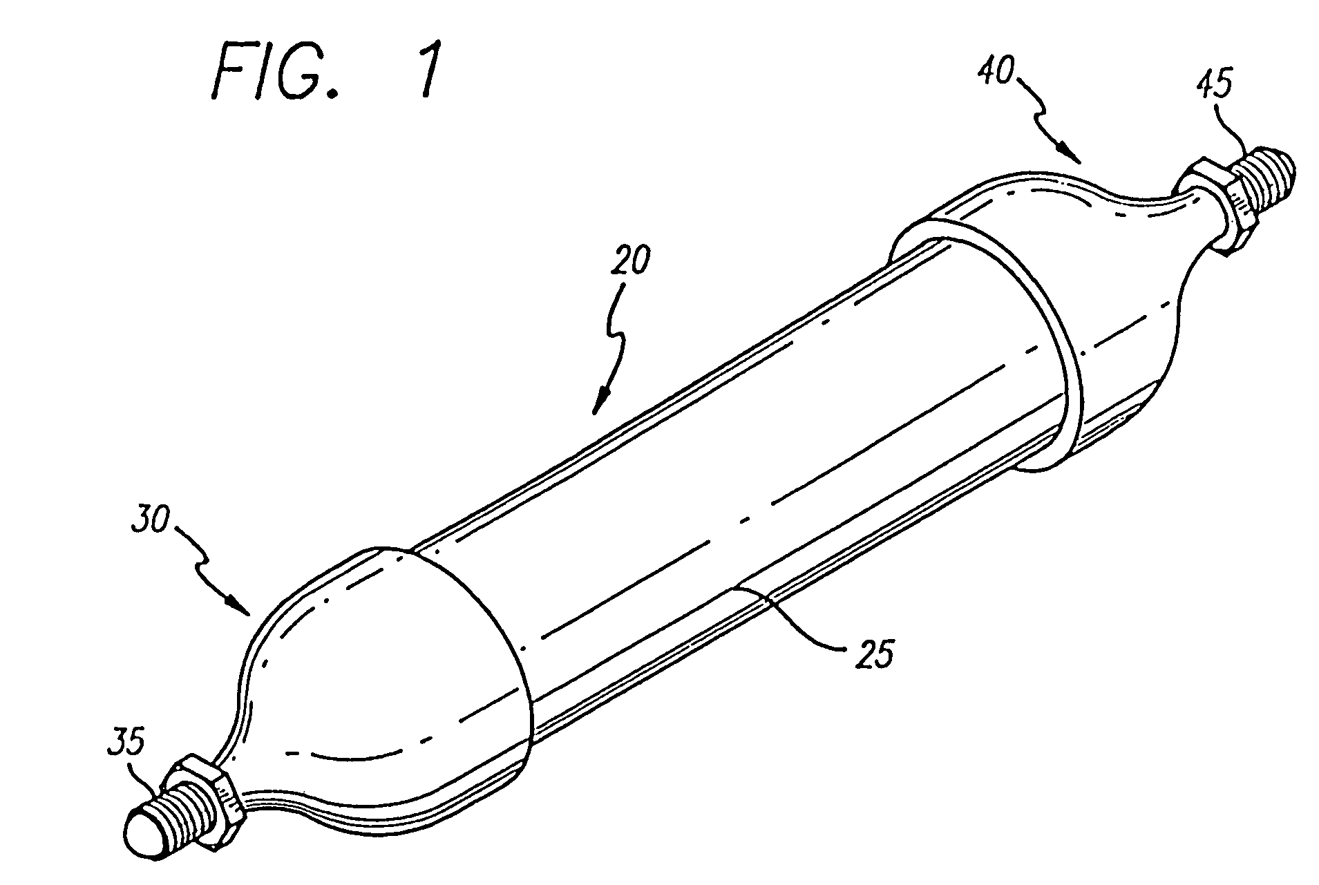
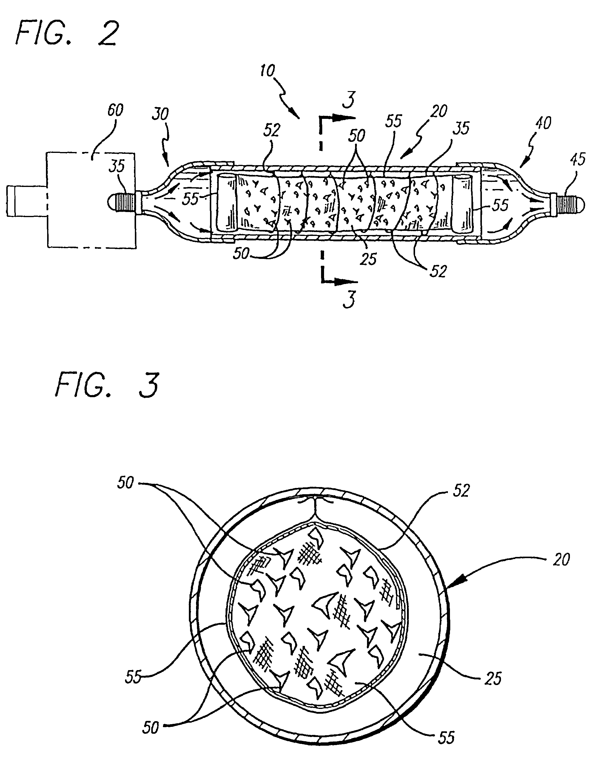
[0028]Shown throughout the figures, the present invention is directed towards a fuel conditioning assembly, generally indicated as 10. The fuel conditioning assembly 10 is structured to be connected in line with an engine or other combustion based system's fuel system in order to effectively treat and condition the fuel prior to its combustion therein, thereby ensuring that a more effective, more efficient burn is achieved.

[0029]In particular, the fuel conditioning assembly 10 includes a housing 20, as shown in the figures. The housing 20, which includes an inlet 30, an outlet 40, is preferably rigid in construction, and includes a generally tubular configuration. The inlet and outlet 30 and 40 may be defined by separate elements fitted onto a main body, or a single cast element generally defining the entire housing 20 may be utilized. Moreover, extending from the inlet 30 of the housing to its outlet 40 is a flow through passage 25, as best shown in FIGS. 2 and 3. As such, fuel is ...


PUM


Abstract

A fuel conditioning assembly having an elongated housing with an inlet, an outlet, and a flow through passage there between. The inlet is coupled with a fuel supply so as to receive fuel flow there through into the flow through passage, wherein a turbulent flow of the fuel is initiated and the fuel is influenced by a combination of elements, in compound or elemental form, some of which are maintained in a select location within the flow through passage by a binding element. These elements may include copper, aluminum, stainless steel, titanium, magnesium, barium, calcium, iron, zirconium, cerium, platinum, and / or palladium which chemically condition the fuel flowing through the flow through passage by rearranging the molecular bonds of the fuel with a catalytic effect. The fuel, regardless of its type is dispersed into very small droplets having high surface areas thereby lowering the vapor density of the fuel and substantially increasing a fuel burn efficiency. Further, the reaction of a variety of these elements, at least with one another, serves to create an electrostatic charge that is conveyed through the flow through passage by an elongate segment and causes fuel molecules to repel one another resulting in the aforementioned catalytic effect and conditioning of the fuel as it passes through the outlet into to any of a variety of fuel combustion assemblies.

Description

CLAIM OF PRIORITY[0001]The present application is a Continuation-In-Part of U.S. patent application Ser. No. 10 / 419,655, filed on Apr. 21, 2003 now U.S. Pat. No. 6,915,789, which is a Continuation-In-Part of U.S. patent application Ser. No. 09 / 934,229, filed on Aug. 21, 2001 now U.S. Pat. No. 6,650,460, which is a Continuation-In-Part application of Ser. No. 09 / 557,705 filed on Apr. 25, 2000, which matured into U.S. Pat. No. 6,276,346 on Aug. 21, 2001, which is a Continuation-In-Part application of Ser. No. 09 / 249,878 filed on Feb. 16, 1999, which matured into U.S. Pat. No. 6,053,152 on Apr. 25, 2000, which is a Continuation-In-Part of Ser. No. 08 / 782,348 filed on Jan. 13, 1997, now U.S. Pat. No. 5,871,000 issued on Feb. 16, 1999, wherein all of the above are incorporated herein, in their entirety, by reference.BACKGROUND OF THE INVENTION[0002]1. Field of the Invention[0003]The present invention relates to a fuel conditioning assembly for use in a fuel combustion system, which is su...

Claims


Application Information

Patent Timeline
Patent Type & Authority Patents(United States)
IPC IPC(8): F02M33/00F02M27/02
CPCF02M27/02
Inventor RATNER, LEGAL REPRESENTATIVE, JOEL S.RATNER, DECEASED, LEE
Owner ROYCE WALKER
Why Eureka
Try Eureka