Cataract imaging apparatus

a technology of cataracts and imaging apparatuses, applied in the field of cataracts, can solve the problems of reducing the contrast of the scene viewed, difficulty in determining when it is appropriate to perform surgery to remove cataracts, and affecting vision, so as to minimize the localized region of the retina, the effect of improving the contrast of the optical imag

Inactive Publication Date: 2007-01-02
VISUAL PATHWAYS
View PDF53 Cites 27 Cited by
  • Summary
  • Abstract
  • Description
  • Claims
  • Application Information

AI Technical Summary

Benefits of technology

[0010]In another aspect of the invention, a method of imaging cataracts in an eye having a cornea, a lens, a pupil, and a retina includes illuminating a localized region of the retina such that light is reflected from the localized region through the pupil of the eye. Light reflected from the localized region of the retina is collected with an optical element. An optical image of the eye is formed on a camera with the optical element so as to produce an electronic image of the eye. The electronic image of the eye is displayed on a monitor. The contrast of the optical image can be improved by minimizing the localized region of the retina that is illuminated.

Problems solved by technology

This light scatter impairs vision because it adds a veiling glare in the retinal image, reducing the contrast of the scene viewed.
Cataract surgery is not entirely without risk, and because cataracts usually develop so slowly, the question of when it is appropriate to perform the surgery to remove them is sometimes difficult.
Surprisingly, as of this writing there is no widely accepted method, either subjective or objective, for determining when surgery is appropriate.
One might expect that measures of visual acuity would be appropriate, but they have been shown not to be useful for making the decision about whether or not to undergo surgery.

Method used


Image

  • Cataract imaging apparatus
  • Cataract imaging apparatus
  • Cataract imaging apparatus

Examples


Embodiment Construction

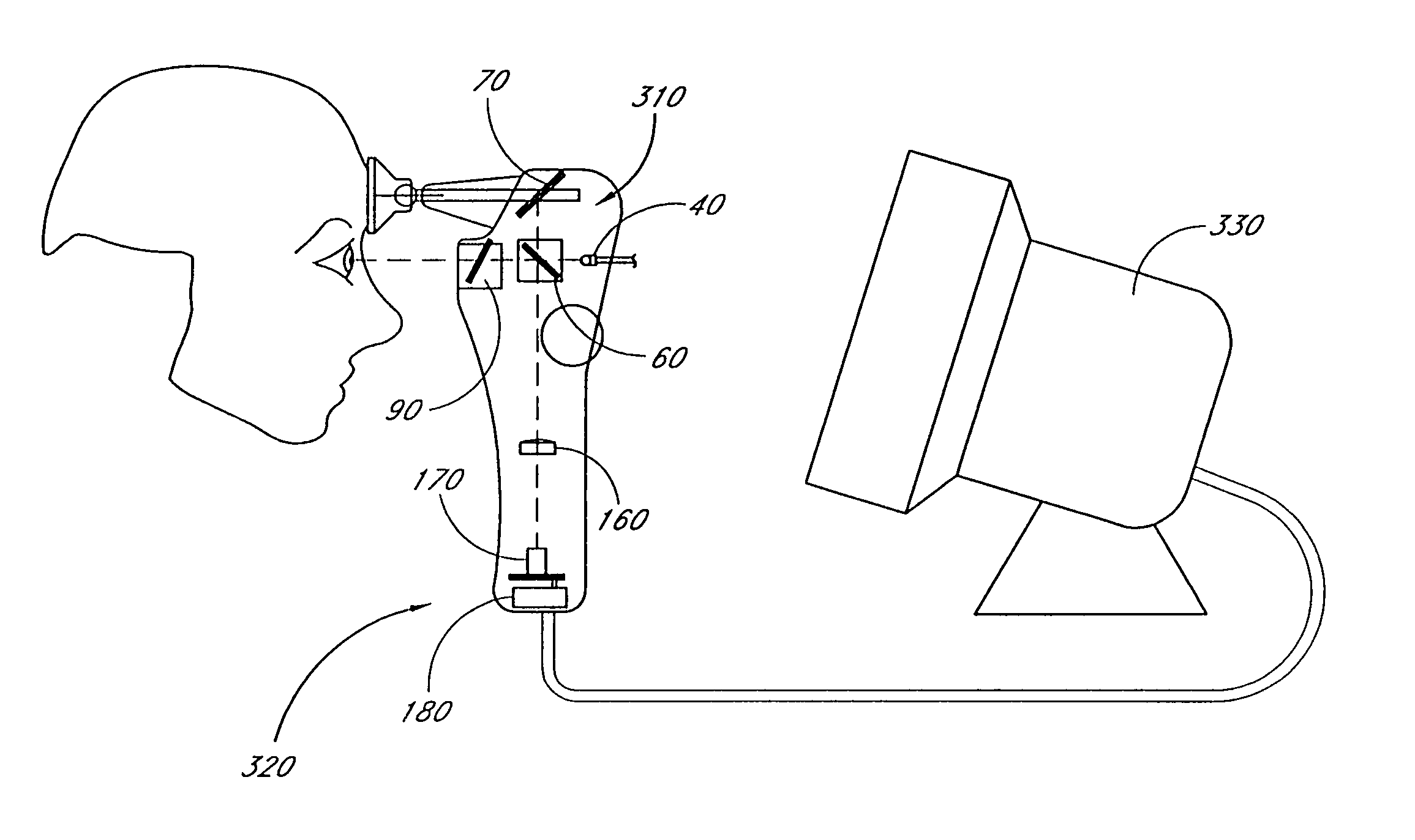
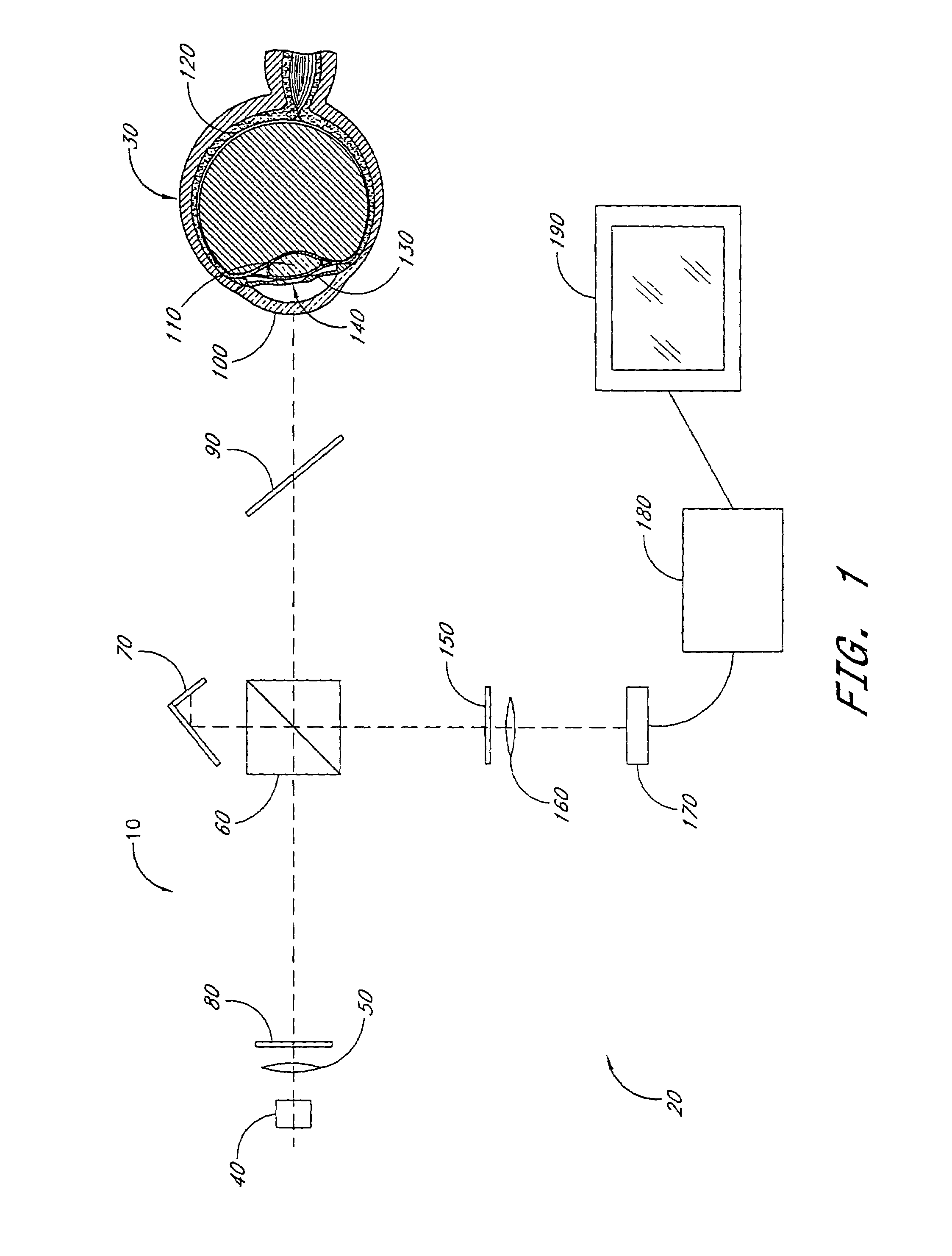
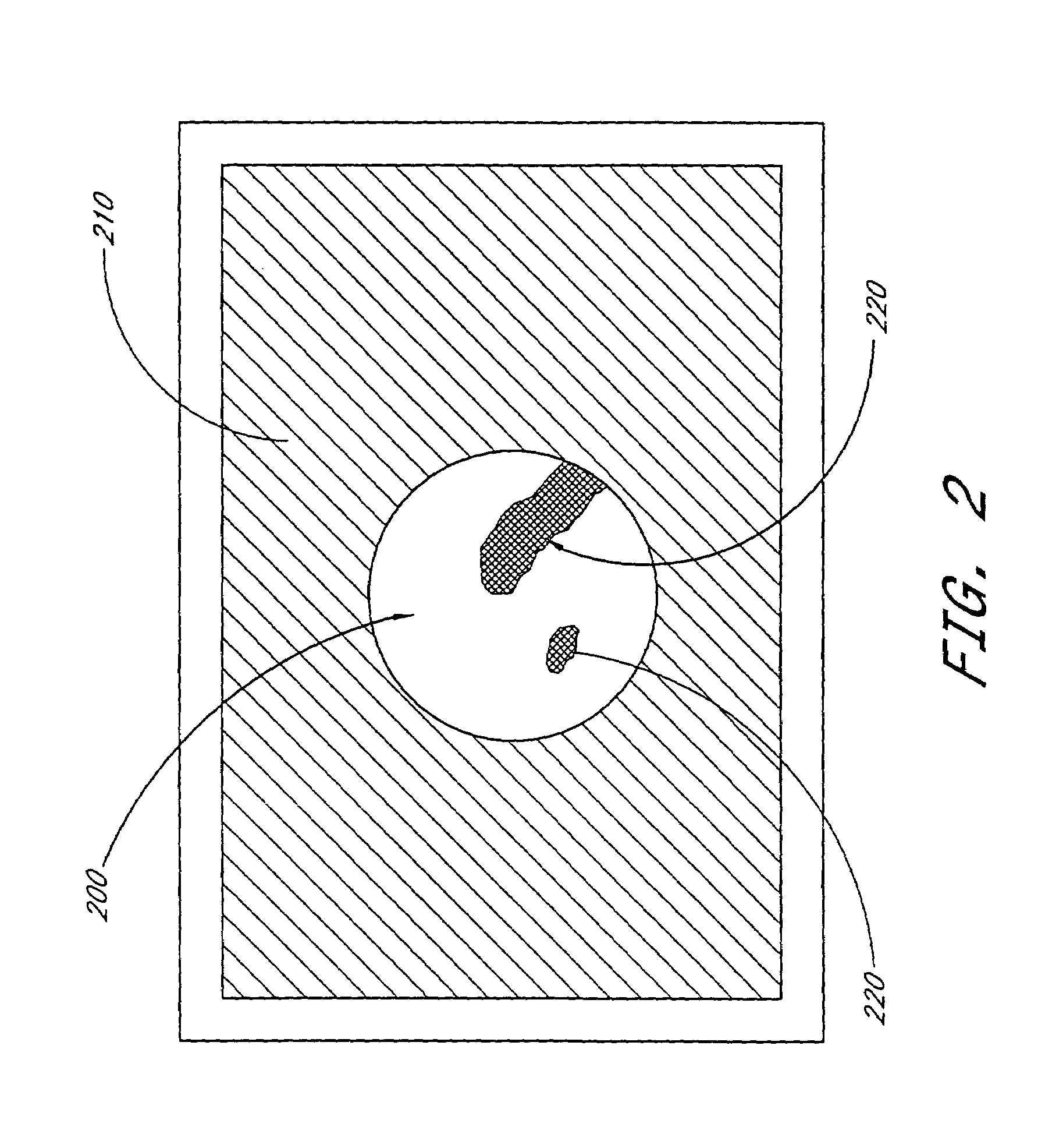
[0023]Various preferred embodiments of instruments and methods described herein use retroillumination of the eye lens, in conjunction with a camera and a display device, and preferably a computer. The arrangement is preferably such that the patient and examiner can both observe a substantially live video or computer image of the patient's cataract, facilitating a discussion of the cataract between the examiner and patient. Automated quantification, for example of the extent and density, of the cataract is preferably performed to provide an objective criterion for deciding whether or not surgery is warranted.

[0024]FIG. 1 is a diagram of the optical components in an optical system 10 comprising one embodiment of an instrument 20 for characterizing an eye 30. Light from a source 40 of near infrared light, preferably an infrared-light-emitting diode (IRLED), passes through a first lens 50, which preferably substantially collimates, or at least substantially reduces the divergence of, th...


PUM


Abstract

A method is disclosed for quantifying the extent a cataract impairs vision in an eye having a pupil, an ocular lens, and a retina. The method includes illuminating a localized region of the retina such that light is reflected from the localized region and is transmitted through the ocular lens. A portion of the reflected light is scattered by the cataract associated with the ocular lens. Light reflected from the localized region of the retina is collected, and the amount of scatter is measured so as to quantify the extent the scatter impairs vision of the eye.

Description

CROSS REFERENCE TO RELATED APPLICATIONS[0001]The present application is a divisional application of a patent application entitled INSTRUMENTS AND METHODS FOR EXAMINING AM) QUANTIFYING CATARACTS, filed Jul. 23, 2002 now U.S. Pat. No. 6,834,958 and assigned Ser. No. 10 / 201,870 and describing an invention made by the present inventor and assigned to the present assignee, which application claims priority to a provisional patent application filed Jul. 23, 2001 and assigned Ser. No. 60 / 307,272.BACKGROUND OF THE INVENTION[0002]1. Field of the Invention[0003]The present invention relates generally to apparatus and methods for characterizing physical properties of an eye and more specifically for characterizing cataracts.[0004]2. Description of the Related Art[0005]The term cataract refers to a reduction in transparency of the lens within the eye. Although some cataracts develop rapidly, the vast majority develop over a period of decades, becoming increasingly prevalent in older populations...

Claims


Application Information

Patent Timeline
Patent Type & Authority Patents(United States)
IPC IPC(8): A61B3/10A61B3/00A61B3/12
CPCA61B3/10A61B3/1176
Inventor CORNSWEET, TOM N.PETERSON, PAUL
Owner VISUAL PATHWAYS
Why Eureka
Try Eureka