Compressor blade for an aircraft engine

a compression blade and aircraft engine technology, applied in the direction of machines/engines, efficient propulsion technologies, liquid fuel engines, etc., can solve the problems of ineffective use of hollow blades in small-power engines, extremely costly manufacturing and economically justifiable blades, and blades of turbomachines, etc., to achieve the effect of large thrust range and light weigh

Inactive Publication Date: 2007-01-02
ROLLS ROYCE DEUT LTD & CO KG
View PDF23 Cites 35 Cited by
  • Summary
  • Abstract
  • Description
  • Claims
  • Application Information

AI Technical Summary

Benefits of technology

[0010]The present invention, in a broad aspect, provides for a type of compressor blade for turbomachines and aircraft engines for a large thrust range which is of light weight and aerodynamically favorable design and which is capable of withstanding the loads arising from a bird strike or from eroding matter, in addition to the operating loads.

Problems solved by technology

The blades of turbomachines, in particular of aircraft engines, are subject to considerable loads arising from centrifugal forces, gas pressure and airfoil vibrations excited by the fluid flow, but also from erosion due to ingested foreign matter or corrosion.
The correspondingly stringent safety requirements are in opposition to the endeavor to cut the manufacturing costs and to lower the specific fuel consumption by reducing the weight of the blades and, hence, of the burst protection elements of the engine.
For weight saving, blades of hollow design are known which, however, are extremely costly to manufacture and economically justifiable only in the case of large engines.
Since the use of hollow-design blades in small-power engines is not effective in terms of the ratio between the achievable weight saving and the cost investment, solid titanium is being used to manufacture the correspondingly smaller blades of such engines.
While these blades withstand the above-mentioned loads, they are susceptible to the vibrations caused by the fluid flow and are also heavy and costly.
Furthermore, blades in fiber compound materials have been developed which, while having a considerable weight advantage over solid blades made of an appropriate metal and possessing appropriate specific strength and high intrinsic damping characteristics against vibrations, do not satisfy the stringent strength criteria as regards erosion or a bird strike to the surface or the leading edge of the airfoil.
While the above-mentioned engine blades possess adequate intrinsic strength, corrosion resistance and vibration damping characteristics in combination with a significantly lower weight than the known solid metal blades, they do not satisfy the stringent safety requirements for erosion resistance and, in particular, impact strength in the event of a bird strike or an impingement of other objects.
The covering structure can be damaged by prolonged erosion or a bird strike, as a result of which the blade core consisting of a fiber compound material may be destroyed.
Furthermore, the known supporting and enveloping structures do not allow an aerodynamically favorable blade geometry to be produced, especially in the air inflow area.

Method used


Image

  • Compressor blade for an aircraft engine
  • Compressor blade for an aircraft engine

Examples


Embodiment Construction

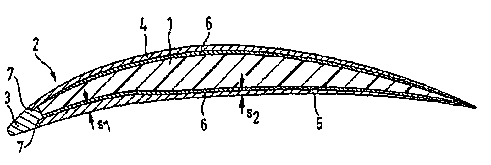
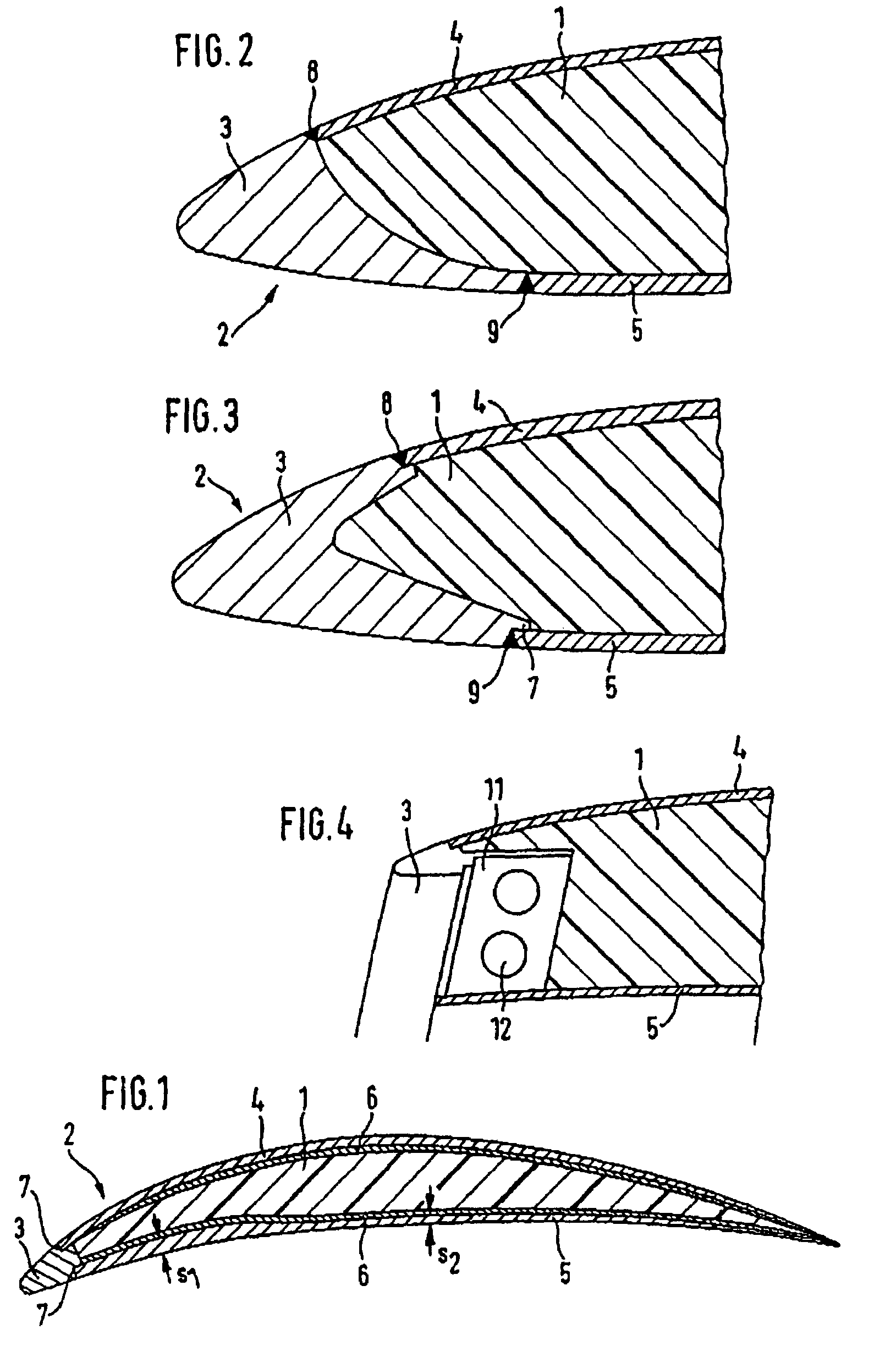
[0020]The compressor blade includes a high-stiffness blade core 1 made of a fiber compound material, a metallic enclosing structure 2 with a leading-edge former 3, and a blade root (not shown) which retains the compressor blade to a disk (not shown).

[0021]The fiber compound material of the blade core serves, in a known manner, for taking up the centrifugal forces and the bending and torsional loads and for vibration damping and provides a weight saving compared to compressor blades made of solid metal. The metallic enclosing structure 2 includes a first blank 5 on the pressure side of the compressor blade and a second blank 4 on the suction side of the compressor blade. On the inner sides of the blanks 4 and 5 facing the blade core 1, a metallic weave 6 is attached which provides for an intimate, firm tie between the blanks 4 and 5 and the fiber compound material of the blade core 1. Alternatively, this intimate tie between the blanks and the fiber compound material can be pretreate...


PUM

PropertyMeasurementUnit
areaaaaaaaaaaa
pressureaaaaaaaaaa
thicknessesaaaaaaaaaa

Abstract

A compressor blade for an aircraft engine includes a blade core made of a fiber compound material and a metallic enclosing structure. The enclosing structure is of a multi-part design and includes blanks (4, 5) attached to the blade core by a metallic weave (6) on the suction side and on the pressure side, with the two blanks being firmly connected at the aerodynamically shaped leading edge of the compressor blade by to a leading-edge former (3). Depending on the specific loads applied on the pressure side and on the suction side, welds attaching the blanks to the leading-edge former (8, 9) are offset relative to each other and the material thicknesses of the components of the enveloping structure are matched to each other.

Description

[0001]This application claims priority to German Patent Application DE10307610.7 filed Feb. 22, 2003, the entirety of which is incorporated by reference herein.BACKGROUND OF THE INVENTION[0002]This invention relates to a compressor blade for an aircraft engine whose airfoil comprises a blade core made of a fiber compound material and a metallic enclosing structure.[0003]The blades of turbomachines, in particular of aircraft engines, are subject to considerable loads arising from centrifugal forces, gas pressure and airfoil vibrations excited by the fluid flow, but also from erosion due to ingested foreign matter or corrosion. The compressor blades, especially the fan blades, of aircraft engines are additionally loaded to a considerable extent by the impingement of birds in the event of a bird strike. The correspondingly stringent safety requirements are in opposition to the endeavor to cut the manufacturing costs and to lower the specific fuel consumption by reducing the weight of t...

Claims


Application Information

Patent Timeline
Patent Type & Authority Patents(United States)
IPC IPC(8): F01D5/14B23P15/04B64C11/20F01D5/28F04D29/02F04D29/32
CPCB23P15/04B64C11/205F01D5/147F01D5/282F04D29/023F04D29/324F05D2240/303F05D2300/171F05D2300/614F05D2300/133F05D2300/16Y02T50/60
Inventor SCHREIBER, KARL
Owner ROLLS ROYCE DEUT LTD & CO KG
Why Eureka
Try Eureka