This helps you quickly interpret patents by identifying the three key elements:
Problems solved by technology
Method used
Benefits of technology
Benefits of technology
[0012]The present invention has been developed in order to overcome the foregoing problems. Objects of the present invention are therefore to provide a reforming apparatus which can show a high efficiency and an excellent operation-starting performance, in spite of its compact and simple configuration, and to provide a method of operating the reforming apparatus, by which the operation of the reforming apparatus can be appropriately started and the purging of a combustible gas can be fully done at the time of stopping the operation.
Problems solved by technology
However, the reforming apparatus shown in FIG. 20 has the following problems, since the reforming reactor (46), the shift reactor (48) and the CO-selective oxidizing reactor (50) are arranged separately from one another: heat release from the reactors (46, 48, 50) leads to larger heat loss, resulting in a poor heat efficiency; because of the above separate arrangement, the heating burners (51, 52, 53) must be provided on the reactors (46, 48, 50), respectively, which results in a complicated apparatus, and also requires a larger amount of energy to start the operation of the apparatus, which results in a poor starting performance.
However, the reforming apparatus shown in FIG. 21 has a problem in its complicated structure because of the multi-cylindrical structure comprising a number of cylinders.
However, the reforming apparatus shown in FIG. 22 has a problem in its poor heat efficiency as follows: The relatively high temperature of the reforming reaction section (72), and the relatively low temperatures of the shift reaction section (73) and the selective oxidizing section (74) are suitably controlled, respectively, by disposing a partition portion (75) between the inner cylinder (70) and the outer cylinder (71) so as to control a quantity of transferred heat.
Therefore, quantities of heat of the reformed gases in the inner cylinder (70) and the outer cylinder (71) are not sufficiently recovered and used, which results in a poor heat efficiency.
Method used
Image
Click on the blue label to locate the original text in one second.
Reading with bidirectional positioning of images and text.
Examples
first embodiment
[0094]In the first embodiment, the reforming apparatus according to the first aspect of the present invention comprises a reformed gas-producing passage for producing a reformed gas from a fuel gas and steam, and a combustion gas passage, wherein
[0095]the reformed gas-producing passage comprises (1) a reforming catalyst section, (2) a shift catalyst section and (3) a CO-selective oxidizing catalyst section, which are arranged as listed order from an upstream side to a downstream side of a flow direction of the reformed gas,
[0096]the reformed gas-producing passage comprises (a) a first passage located adjacent to the combustion gas passage and including the reforming catalyst section, and (b) a second passage located adjacent to the first passage,
[0097]the second passage comprises a first heat-recovering section located adjacent to the reforming catalyst section, and
[0098]the first passage comprises a second heat-recovering section located adjacent to at least one of the shift cataly...
third embodiment
[0111]In the third embodiment, the reforming apparatus according to the first aspect of the present invention as described above comprises:
[0112]a reformed gas-producing passage which includes a reforming catalyst section for producing a reformed gas containing hydrogen as a main component by steam-reforming a fuel gas and steam, a shift catalyst section for reducing the CO in the reformed gas produced in the reforming catalyst section through a water gas shift reaction, and a CO-selective oxidizing catalyst section for further reducing the CO in the reformed gas having undergone the water gas shift reaction by reacting the CO in the reformed gas with oxygen, which sections are arranged in such listed order along the gas flow direction; and
[0113]a combustion gas passage for heating the reforming catalyst section, and
[0114]this reforming apparatus is characterized in
[0115]that the reformed gas-producing passage comprises:
[0116]a first passage including the reforming catalyst section ...
fifth embodiment
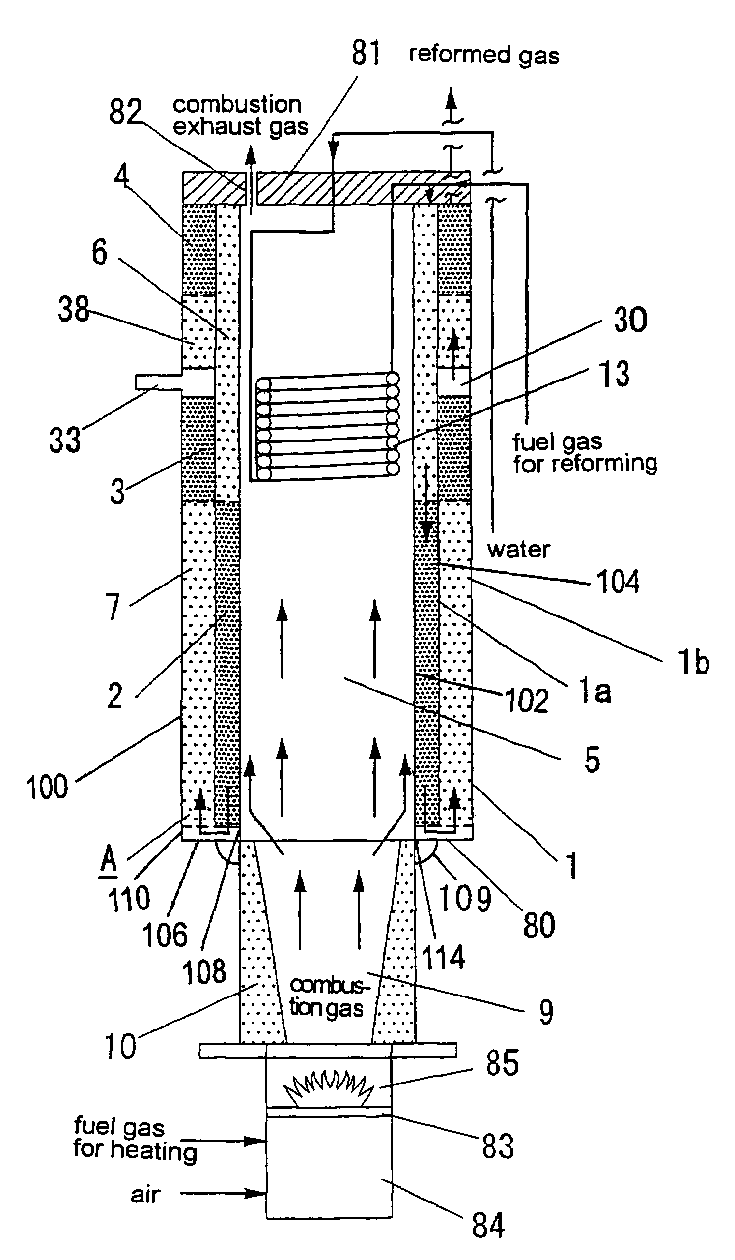
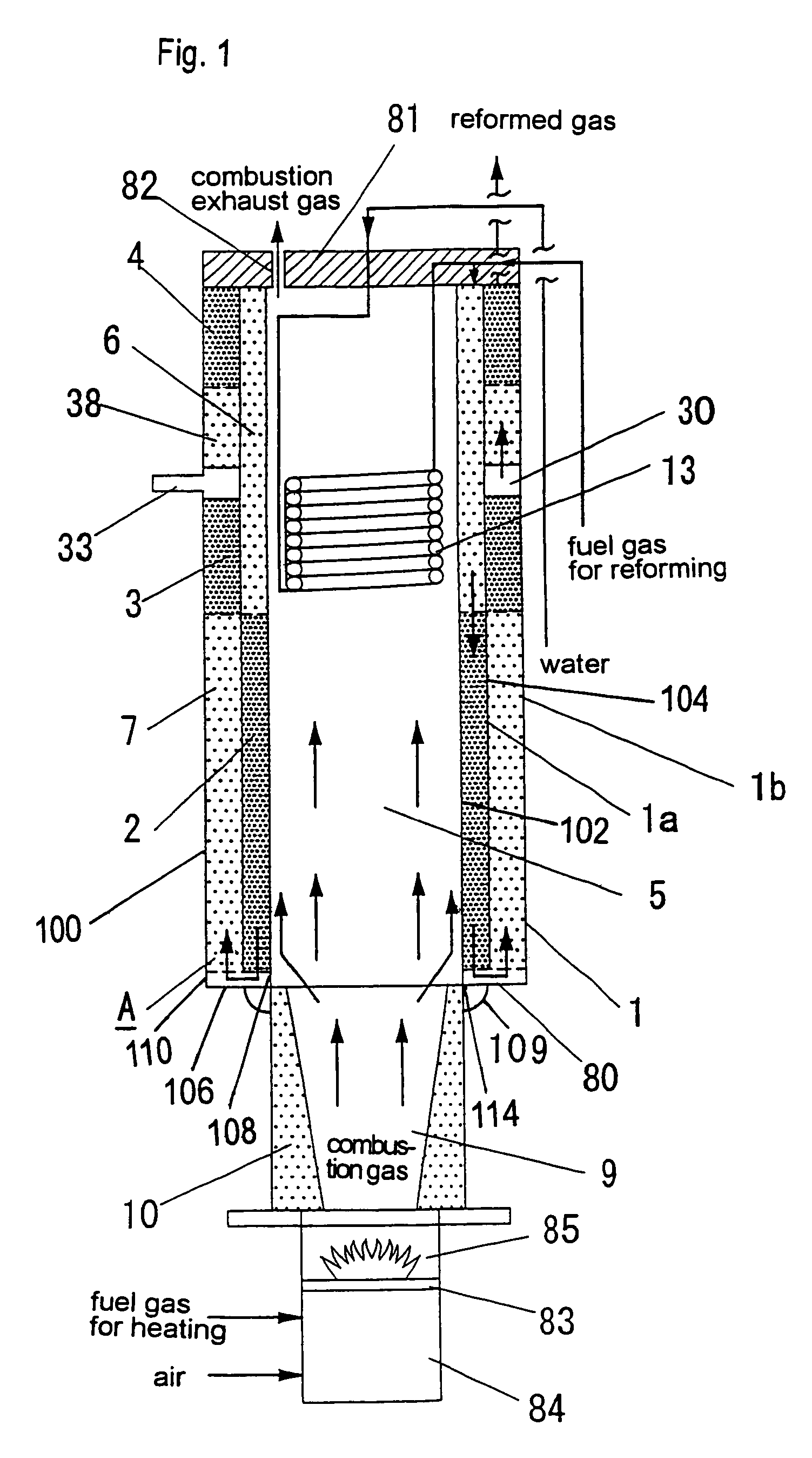
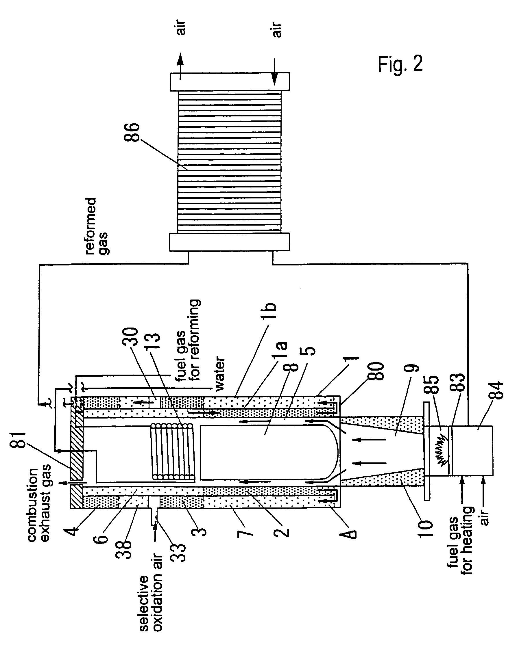
[0177]There is no particular limit in the shape of the reformed gas-producing passage (1). However, a compact reforming apparatus with a decreased number of layers and not so complicated structure can be provided by cylindrically forming a first passage (1a) and a second passage (1b), thereby forming a reformed gas-producing passage (1) in the shape of a concentric double cylindrical body. The second outer passage (1b) includes a first heat-recovering section (7), a shift catalyst section (3), a third heat-recovering section (38) and a CO-selective oxidizing catalyst section (4) which require relatively low temperatures. With this arrangement, the loss of heat release to the outer peripheral area is reduced, so that the apparatus can achieve a high heat efficiency.
PUM
Property
Measurement
Unit
Heat
aaaaa
aaaaa
Abstract
A reforming apparatus for producing a reformed gas from a fuel gas and steam, including a reformed gas-producing passage and a combustion gas passage, the reformed gas-producing passage having reforming catalyst, shift catalyst, and CO-selective oxidizing catalyst sections along a flowing direction of the reformed gas, the reformed gas-producing passage having a first passage adjacent to the combustion gas passage and including the reforming catalyst section and a second passage adjacent to the first passage, the second passage including a first heat-recovering section adjacent to the reforming catalyst section, and the first passage having a second heat-recovering section adjacent to one of the shift catalyst and CO-selective oxidizing catalyst sections, the first heat-recovering section located on an upstream side along the flow direction of the reformed gas relative to the reforming catalyst section.
Description
FIELD OF THE INVENTION[0001]The present invention relates to a reforming apparatus which steam-reforms a fuel gas to produce a hydrogen-rich reformed gas and which simultaneously reduces a concentration of carbon monoxide in the reformed gas.BACKGROUND ART[0002]In the field of fuel cell generation systems, there are used reforming apparatuses which produce reformed gases containing hydrogen as a main component by steam-reforming a fuel gas as a raw material (e.g. alcohols such as methanol etc., hydrocarbons such as methane, buthane, etc., fossil fuels such as naphtha, LNG, etc.).[0003]FIG. 20 shows one of the reforming apparatuses disclosed in Japanese Patent Kokai Publication No. 2001-180911. This reforming apparatus comprises a reforming reactor (46) charged with a reforming catalyst (45), a shift rector (48) charged with a shift catalyst (47), and a CO-selective oxidizing reactor (50) charged with a CO-selective oxidizing catalyst (49), which are arranged separately from one anot...
Claims
Application Information
Patent Timeline
Application Date:The date an application was filed.
Publication Date:The date a patent or application was officially published.
First Publication Date:The earliest publication date of a patent with the same application number.
Issue Date:Publication date of the patent grant document.
PCT Entry Date:The Entry date of PCT National Phase.
Estimated Expiry Date:The statutory expiry date of a patent right according to the Patent Law, and it is the longest term of protection that the patent right can achieve without the termination of the patent right due to other reasons(Term extension factor has been taken into account ).
Invalid Date:Actual expiry date is based on effective date or publication date of legal transaction data of invalid patent.

