Low pressure drop deep electrically enhanced filter

a technology of low pressure drop and filter media, which is applied in the direction of filtration separation, other chemical processes, separation processes, etc., can solve the problems of undetectable reduction of the surface area of the filter media available, the limitation of the cheney'736 to use such separators, and the construction of embodiments according to the principles, etc., to achieve effective and safe electrically enhanced filters, high efficiency filtration, and high dust holding capacity

Inactive Publication Date: 2007-01-02
JAISINGHANI RAJAN A
View PDF37 Cites 47 Cited by
  • Summary
  • Abstract
  • Description
  • Claims
  • Application Information

AI Technical Summary

Benefits of technology

[0017]It is another object to provide electrically enhanced filtration with a deep filter exhibiting high surface area in a manner that enables the creation of stable and uniform collection field strengths while suppressing arcing across the filter media.
[0025]It is an additional object to enable high efficiency filtration with higher dust holding capacity and thus life of the filter, by electrically enhancing the performance of deep V-pack filter elements.

Problems solved by technology

Embodiments constructed according to the principles of U.S. Pat. No. 5,403,383 are limited as a practical matter, to relatively shallow filter media with peak-to-peak depths of about six inches.
Cheney '736 is limited to using such separators as electrodes within folded dielectric filter media in paper form.
I have found that this undesirably reduces the surface area of filter media available to remove particles from the air flow, principally due to the fact that these spacers have a minimum depth to the corrugations which restricts the number of pleats that can be used within an available volume.
Another problem that I have discovered, related to the use of aluminum separators, is that under fluctuating flow or start up flow conditions these sharp corrugated separators can cut the delicate fiber glass media used in such filters, causing damage and leakage within the filter media.
I have noticed that there are problems with parallel ionizer plates attributable to dust particles of opposing charge that tend to accumulate on the ionizer plates because the dust particles have to travel only across the direction of the air flow in order to accumulate on the plates.
Embodiments of Masuda are highly prone to arcing.
The use of organic materials for the frames as suggested by Cheney '736 is rather dirty, and thus undesirable for clean room applications.
These practical difficulties and limitations upon performance are the main reason why a device such as taught by Cheney '736 has never been successfully commercialized.
Additionally, aluminum separator folded filter type filter elements have become unpopular because this type of filter element tends to tear due to the sharp edges of the aluminum separators within the folded medium.

Method used


Image

  • Low pressure drop deep electrically enhanced filter
  • Low pressure drop deep electrically enhanced filter
  • Low pressure drop deep electrically enhanced filter

Examples


Embodiment Construction

[0048]As used in this description, the variable:[0049]d1 represents the distance between the ground control electrode 7 and the ionizing electrodes 8;[0050]d2 represents the separation between the charge transfer electrodes 8 and the ionizing electrodes 5;[0051]d3 represents the distance between the downstream ground electrodes 4 and the charge transfer electrodes 5;[0052]d4 represents the nominal depth of each fold as illustrated, by way of example, in FIG. 12, of the filter medium 1, 16 or 17, as measured between the base of the fold to the longitudinally opposite apex of the fold; and[0053]d5 represents the nominal width of the base of each fold as exemplified by FIG. 12, as measured between successive upstream apices of a fold.

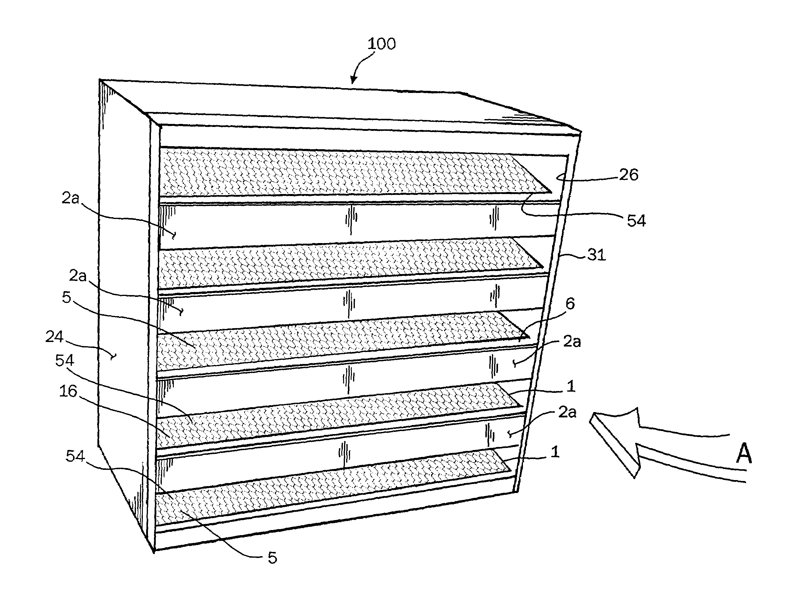
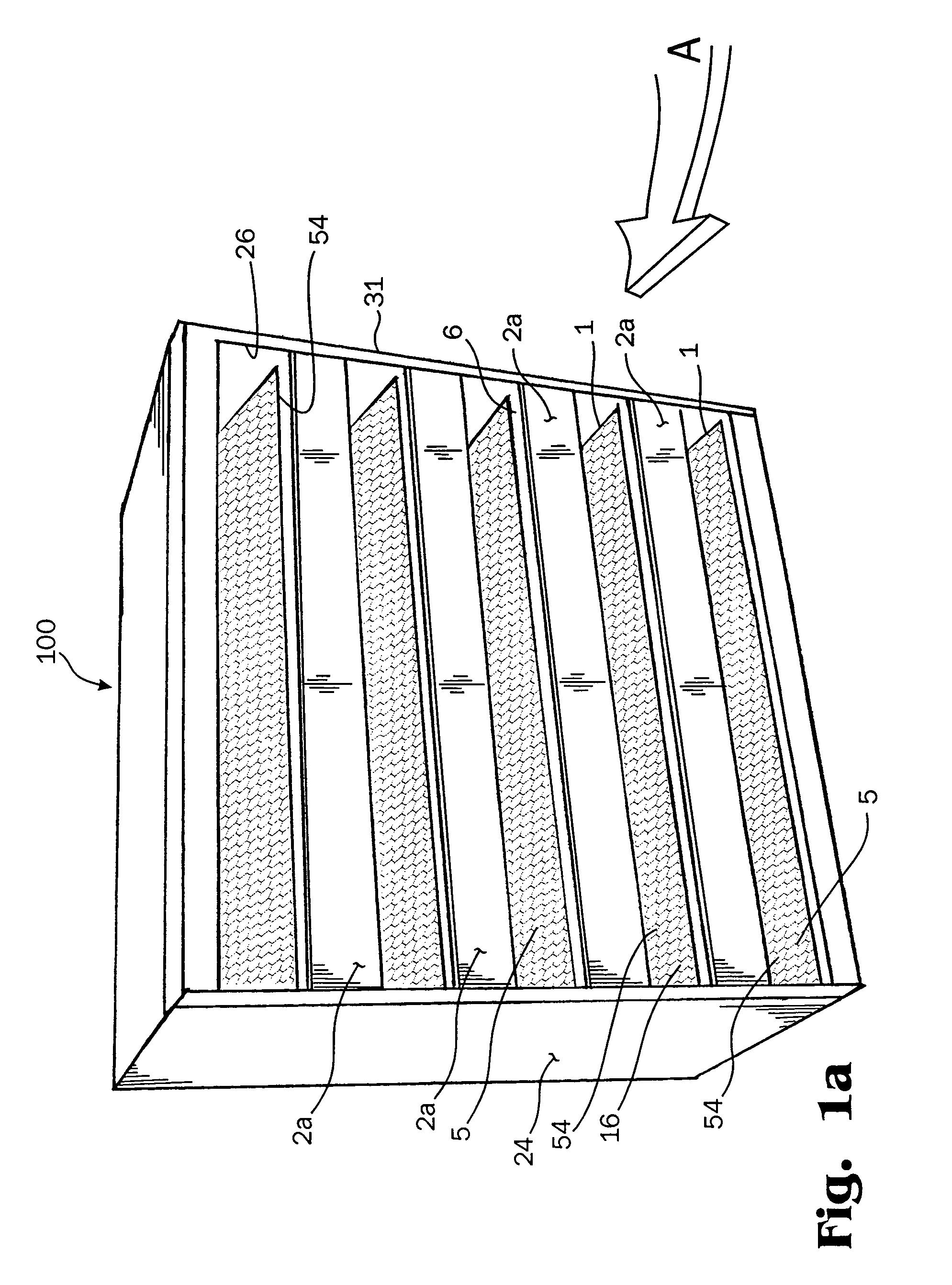
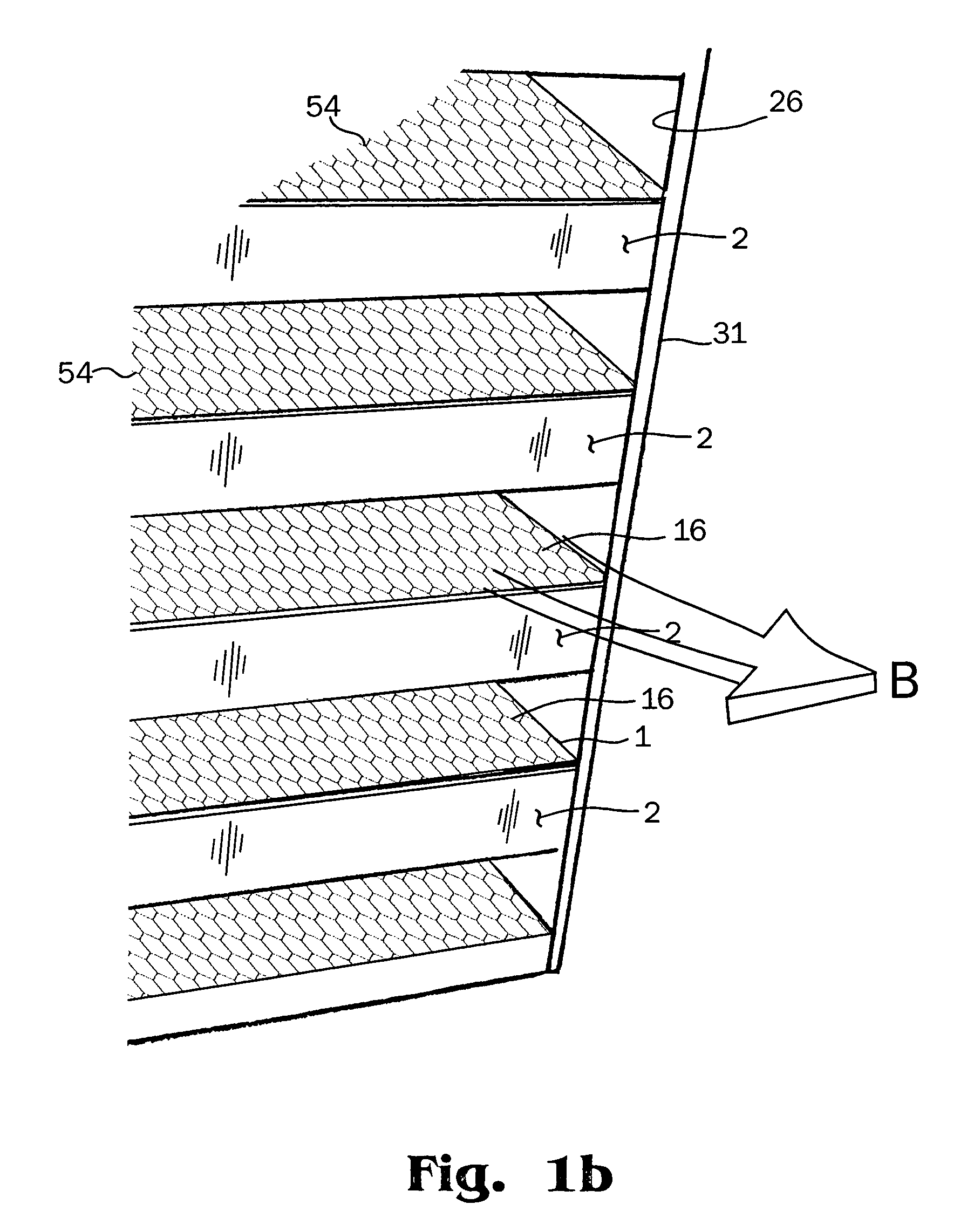
[0054]Turning now to the drawings collectively, and particularly to FIG. 1a, which shows an elevation view of an inlet side of a filter assembly 31 for an ionizing field electronically enhanced filter 100 with the ionizer assembly removed, FIG. 1b which sh...


PUM

PropertyMeasurementUnit
peak-to-peak depthsaaaaaaaaaa
particle sizeaaaaaaaaaa

Abstract

A method and apparatus using deep pleated filters to provide efficient and safe electrically enhanced filtering (EEF), with ultra low pressure drop, higher efficiency of particulate removal and higher dirt holding capacity over the life of the filter. An EEF may be constructed with a housing, with or without an internal air moving device such as a fan, a deeply pleated filter, preferably a V-pack filter with sets of downstream ground electrodes and charge transfer electrodes borne by the exterior surface of the filter packs that form the filtering element. An ionizer assembly that ionizes the gas and charges particles entering the deeply pleated filter and also transfers a charge to the charge transfer electrodes on the filter pack. A plate seals the gasket on the filtering element against the ionizing assembly. A high electrical potential is applied to charging elements in the ionizer and, in some embodiments, a fan or motor assembly. The charge transfer electrodes enable the device to function with a high particle collection field between the charge transfer electrodes and the downstream grounded electrodes to safely and efficiently attain higher entrapment of the particles on the filter medium.

Description

CLAIM FOR PRIORITY[0001]This application makes reference to, claims all benefits inuring under 35 U.S.C. §111(b) from, and incorporates herein my provisional patent application entitled Low Pressure Drop Deep Electrically Enhanced Filter earlier filed in the United States Patent and Trademark Office on the 12th day of Jul. 2002 and there duly assigned Ser. No. 60 / 395,322, my provisional patent application entitled Low Pressure Drop Deep Electrically Enhanced Filter earlier filed in the United States Patent and Trademark Office on the 10th day of Feb. 2003 and there duly assigned Ser. No. 60 / 437,140, and my provisional patent application entitled Low Pressure Drop Deep Electrically Enhanced Filter earlier filed in the United States Patent and Trademark Office on the 25th day of Apr. 2003 and there duly assigned Ser. No. 60 / 465,277.BACKGROUND OF THE INVENTION[0002]1. Technical Field[0003]This application pertains to filters and filtration processes and systems generally and, more part...

Claims


Application Information

Patent Timeline
Patent Type & Authority Patents(United States)
IPC IPC(8): B03C3/155B03C3/09
CPCB03C3/09B03C3/12B03C3/155Y10S264/48Y10S55/05
Inventor JAISINGHANI, RAJAN A.
Owner JAISINGHANI RAJAN A
Why Eureka
Try Eureka