
High capacity flash vapor generation systems

a vapor generation system and high-capacity technology, applied in the field of sterilization arts, can solve the problems of difficult and time-consuming degassing of gas absorption materials in the decontaminated room or building, high toxic chlorine dioxide, and the need to recover toxic gases from dilution air, so as to achieve the effect of reducing the amount of contaminated materials, and increasing the air flow and hydrogen peroxide injection ra

Active Publication Date: 2007-01-02
AMERICAN STERILIZER CO
View PDF10 Cites 27 Cited by
  • Summary
  • Abstract
  • Description
  • Claims
  • Application Information

AI Technical Summary

Benefits of technology

[0014]One advantage of the present invention is that a high output of vaporized hydrogen peroxide is achieved.
[0015]Another advantage of the present invention is that the air flow and hydrogen peroxide injection rates can be increased.
[0016]Another advantage resides in the ability to decontaminate larger volumes.
[0017]Another advantage of the present invention is that it enables peroxide concentration levels to be raised rapidly to sterilization levels, particularly when used with smaller enclosures, thereby reducing the conditioning time.
[0018]Still further advantages of the present invention will become apparent to those of ordinary skill in the art upon reading and understanding the following detailed description of the preferred embodiments.

Problems solved by technology

However, chlorine dioxide is highly toxic and must be recovered from the microbial decontamination process.
Recovery of toxic gases from dilution air, leaking air, and the degassing of gas absorptive materials in the decontaminated room or building is difficult and time consuming.
The capacity of the vaporizer is limited in a number of ways.
First, the vaporization process creates a pressure increase, reducing the flow of air through the vaporizer.
Second, to maintain sterilization efficiency, the pressure at which the vapor is generated is limited to that at which the hydrogen peroxide is stable in the vapor state.
However, the carrier gas tends to cool the heating surface, disrupting the vaporization process.
However, the use of multiple vaporizers adds to the cost of the system and requires careful monitoring to ensure that each vaporizer is performing with balanced efficiency.

Method used


Image

  • High capacity flash vapor generation systems
  • High capacity flash vapor generation systems
  • High capacity flash vapor generation systems

Examples


Embodiment Construction

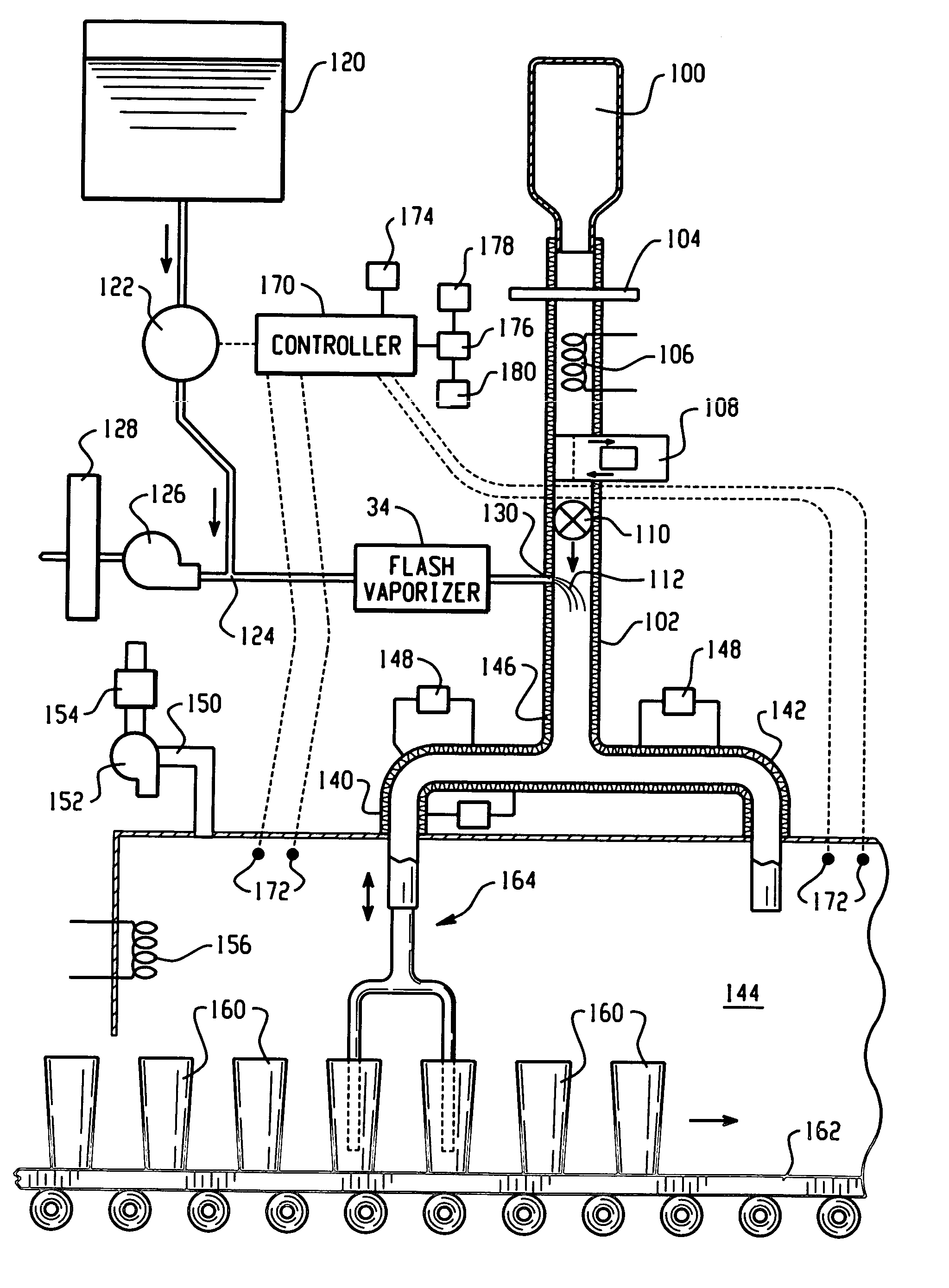
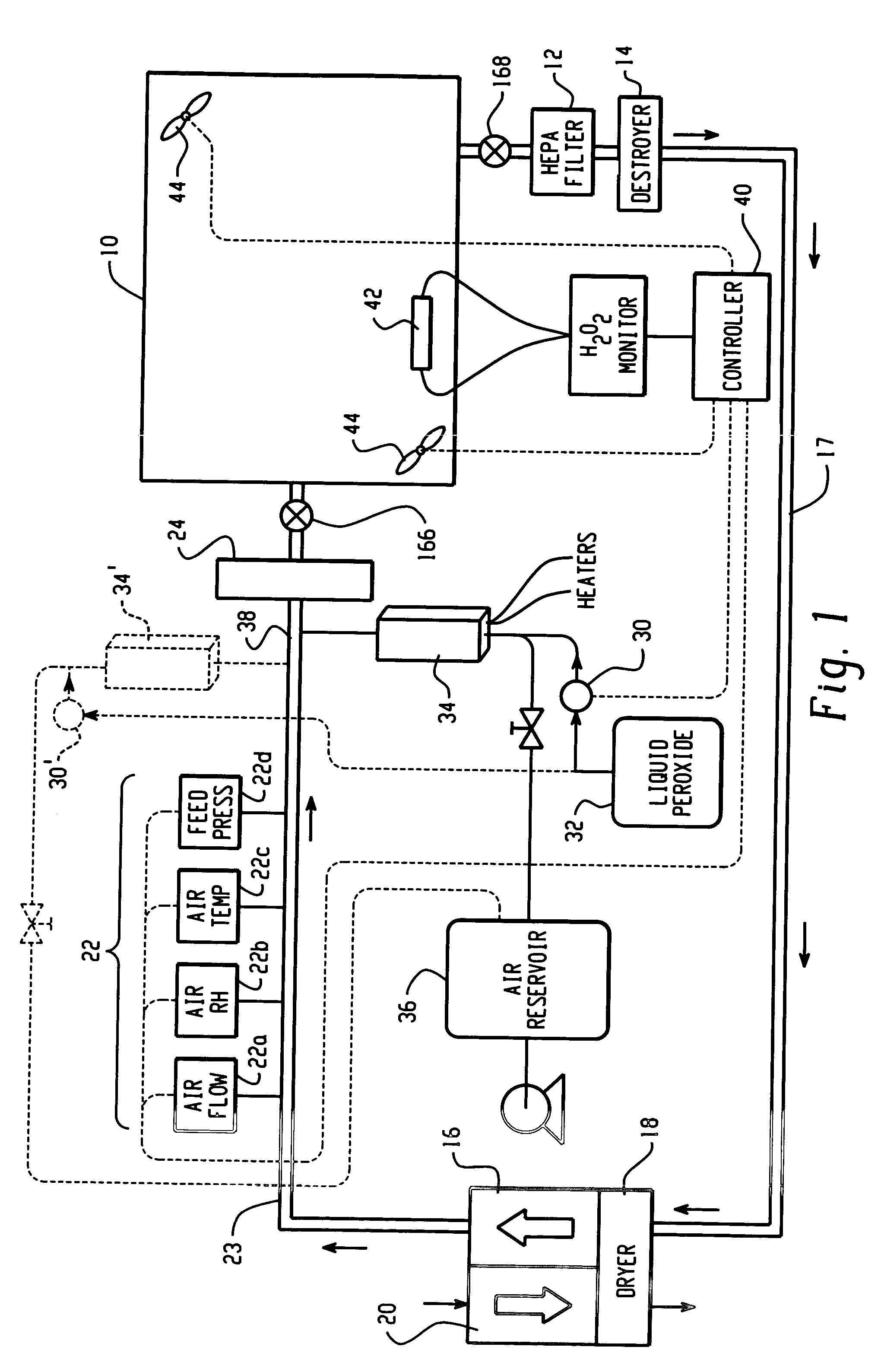
[0029]With reference to FIG. 1, a system for microbially decontaminating a room or other defined area with an antimicrobial vapor is shown. While the system is described with particular reference to hydrogen peroxide in vapor form, other antimicrobial vapors are also contemplated, such as vapors comprising peracetic acid or other peroxy compounds, aldehydes, such as formaldehyde vapors, and the like. Air from a large defined region, such as a room 10 with a volume on the order of 1,000–4,000 cubic meters is withdrawn through a contamination removing filter 12 and a peroxide destroying catalyst 14 by a blower 16, which is connected with the filter and destroyer by a duct or line 17. The blower draws the air through a dryer, such as a desiccant wheel 18 which removes the water vapor. A second blower 20 blows heated air through a saturated portion of the desiccant wheel to remove and exhaust the absorbed moisture to the atmosphere. This heating process preferably heats the recirculated...


PUM


Abstract

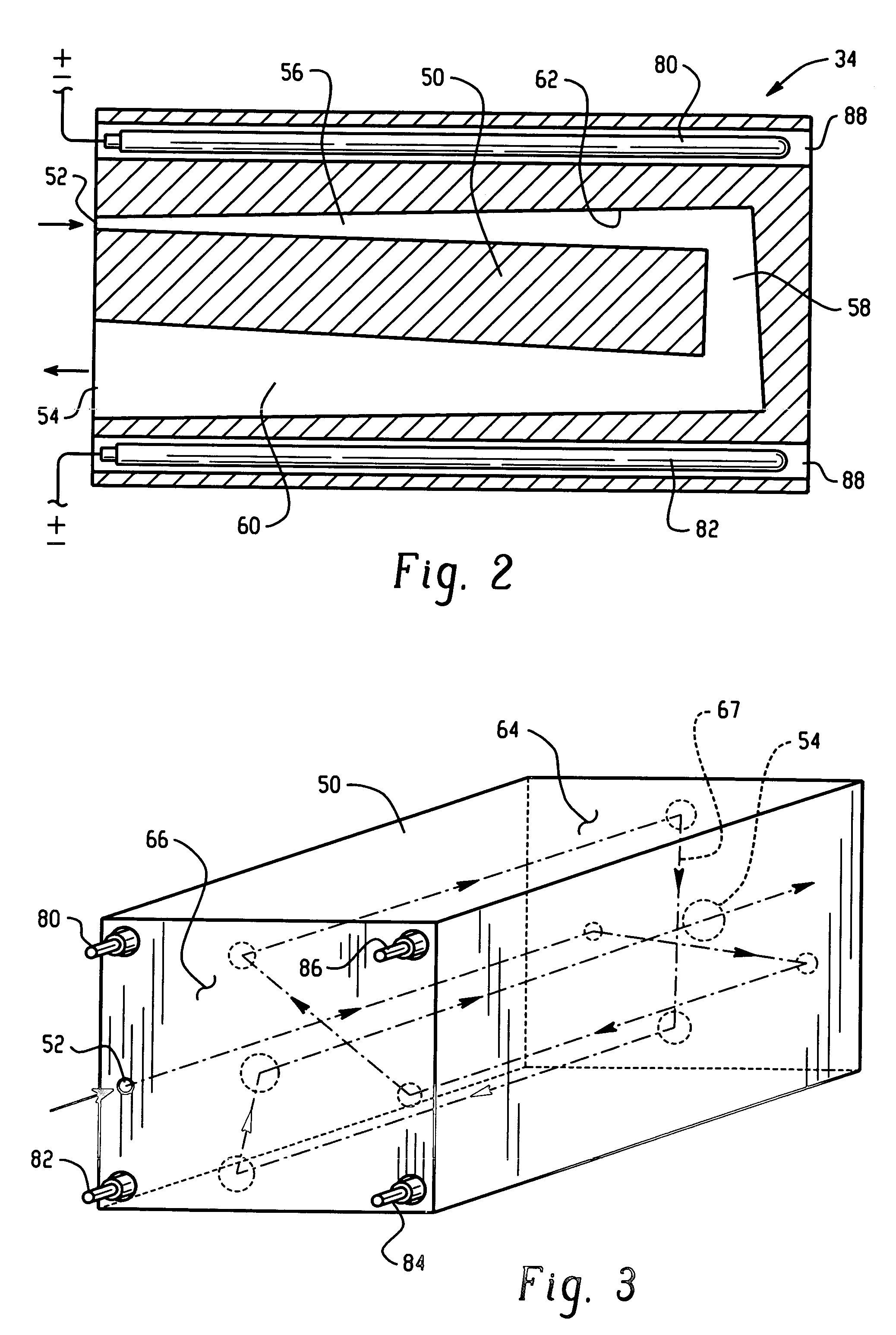
A flash vaporizer (34) provides a constant flow of vaporized hydrogen peroxide or other antimicrobial compounds for rapidly sterilizing large enclosures (10), such as rooms or buildings. The vaporizer includes a heated block (50) which defines an interior bore or bores (70, 72, 74). The flowpath created by the bore or bores increases in cross sectional area as the hydrogen peroxide passes through the block to accommodate the increase in volume during the conversion from liquid to gas. The vapor is injected into dry air in a duct that circulates it to the large enclosure.

Description

[0001]This application claims the benefit of U.S. provisional patent application Ser. No. 60 / 269,659, filed Feb. 16, 2001.BACKGROUND OF THE INVENTION[0002]The present invention relates to the sterilization arts. It finds particular application in conjunction with hydrogen peroxide vapor systems used in connection with the sterilization of rooms, buildings, large enclosures, and bottling, packaging, and other production lines and will be described with particular reference thereto. It should be appreciated, however, that the invention is also applicable to other chemical vaporization systems such as those employing other peroxy compounds or aldehydes, for example, peracetic acid or formaldehyde vaporization systems.[0003]Microbial decontamination of rooms and buildings can be achieved using chlorine dioxide gas. However, chlorine dioxide is highly toxic and must be recovered from the microbial decontamination process. Recovery of toxic gases from dilution air, leaking air, and the de...

Claims


Application Information

Patent Timeline
IPC IPC(8): A61L2/00A61L2/20B65B55/02B65B55/10B67C7/00
CPCA61L2/208B67C7/0073B65B55/025B65B55/10A61L2202/11A61L2202/18A61L2202/23
Inventor MCVEY, IAIN F.ZELINA, FRANCIS J.HILL, AARON L.MCDONNELL, GERALD E.WILLIAMS, KEVIN O.MIELNIK, THADDEUS
Owner AMERICAN STERILIZER CO
Learn More